Tool magazine and tool changing method thereof

A tool magazine and tool technology, applied in the field of machinery, can solve problems such as affecting stability, and achieve the effect of not easy to change the tool and fast tool change.

Inactive Publication Date: 2016-03-16
CHUZHOU SHENYU HYDRAULIC TECH CO LTD
View PDF11 Cites 3 Cited by
  • Summary
  • Abstract
  • Description
  • Claims
  • Application Information

AI Technical Summary

Problems solved by technology

The movement of the overall tool magazine may affect its stability due to inertia on large tools

Method used


Image

  • Tool magazine and tool changing method thereof
  • Tool magazine and tool changing method thereof
  • Tool magazine and tool changing method thereof

Examples


Embodiment Construction

[0031] The present invention will be described in further detail below in conjunction with the accompanying drawings and embodiments. It should be understood that the specific embodiments described here are only used to explain the present invention, not to limit the present invention.

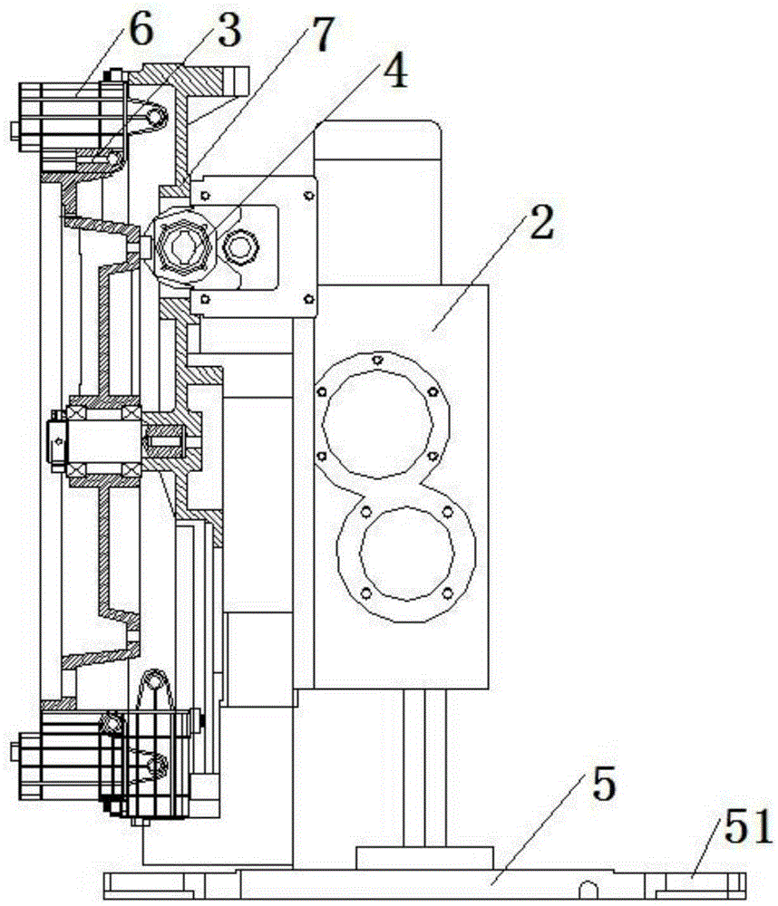
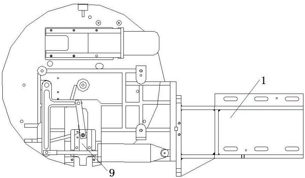
[0032] Such as figure 1 with 2 Shown is a tool magazine, including a support 1, a manipulator control device 2, a base body 7, a turntable 3 and a tool magazine drive device 4 for controlling the change of the tool position of the turntable 3, and the turntable 3 is installed on the base body 7, and The main shaft 8 of the machine tool is at 90°, the manipulator control device 2 is fixedly installed on the base 7, the output end of the manipulator control device 2 is connected with a manipulator 5, and the manipulator 5 is T-shaped, and its two ends are provided with clamping The knife holder 51 of tight tool. The support 1 is installed on the side of the base body 7 for connection with th...


PUM


Abstract

The invention provides a tool magazine. The tool magazine comprises a support (1), a manipulator control device (2), a base body (7), a rotating plate (3) and a tool magazine driving device (4), wherein the tool magazine driving device (4) controls the tool location of the rotating plate (3) to be changed. The rotating plate (3) is installed on the base body (7) to form an angle of 90 degrees with a machine tool spindle (8). The manipulator control device (2) is fixedly installed on the base body (7). A manipulator (5) is connected to the output end of the manipulator control device (2) and in a T shape. Tool holders (51) used for clamping a tool are arranged at the two ends of the manipulator (5). The support (1) is installed on the side face of the base body (7) to be used for being connected with a machine tool vertical post. The tool magazine has the beneficial effects that the manipulator is used for changing the tool, so that the tool magazine has the advantages of being high in tool changing speed, stable, reliable and the like, and the disorder phenomenon of the tool is not prone to happening.

Description

technical field [0001] The invention relates to the mechanical field, in particular to a tool magazine and a tool changing method thereof. Background technique [0002] Traditionally used disc tool magazine see image 3 , the axis of the tool 9 is arranged parallel to the axis of the turntable 10, and the tool magazine is arranged on the side of the column 11 parallel to the main shaft 12. During the tool change process, the main shaft 12 moves up to align with the tool 9, and the main shaft 12 moves to the vacant jaw position of the tool magazine for preparation To change the tool, the tool magazine moves down to pull out the tool on the spindle; the tool magazine rotates to the tool change position required by the program, the tool magazine returns to insert the required tool into the spindle hole, the spindle moves away from the tool magazine, and goes down for processing. This form has a long tool picking stroke, which is generally completed by hydraulic or pneumatic dev...

Claims


Application Information

Patent Timeline
Patent Type & Authority Applications(China)
IPC IPC(8): B23Q3/155
CPCB23Q3/1552B23Q3/15506
Inventor 李志
Owner CHUZHOU SHENYU HYDRAULIC TECH CO LTD
Why Eureka
Try Eureka