Bistable permanent magnet moulded case circuit breaker

A molded case circuit breaker, bistable technology, applied in the protection switch operation/release mechanism, etc., can solve the problems of complex mechanism, increase user burden, reduce the reliability of molded case circuit breaker, etc., to simplify the structure and improve reliability Effect

Inactive Publication Date: 2016-03-09
FORETECH ELEC APP JIANGSU CORP
View PDF11 Cites 2 Cited by
  • Summary
  • Abstract
  • Description
  • Claims
  • Application Information

AI Technical Summary

Problems solved by technology

[0002]At present, the molded case circuit breaker basically adopts the form of a manual operation mechanism plus a release device, and the operating mechanism uses spring energy storage to realize the main circuit of electrical equipment to be connected, Breaking and protection; the patent No. 201510094877.6 "a molded case circuit breaker" realizes electric control based on the original manual molded case circuit breaker through the energy storage method of the rotating motor, and the patent No. 201410829577.3 "circuit breaker electric operation "Mechanism" realizes electric control on the basis of the original manual molded case circuit breaker by means of a linear motor; however, the above-mentioned patents and other existing patents that can realize molded case circuit breakers all use additional mechanisms on the basis of retaining the original operating mechanism Although this form retains the original manual operation function, this method makes the original molded case circuit breaker mechanism more complicated and reduces the reliability of the molded case circuit breaker. Further purchase of auxiliary electronic control mechanism increases the burden on users

Method used


Image

  • Bistable permanent magnet moulded case circuit breaker
  • Bistable permanent magnet moulded case circuit breaker
  • Bistable permanent magnet moulded case circuit breaker

Examples


Embodiment Construction

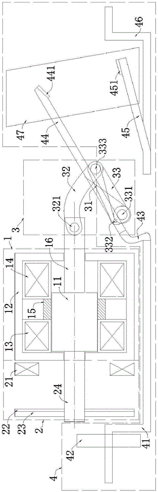
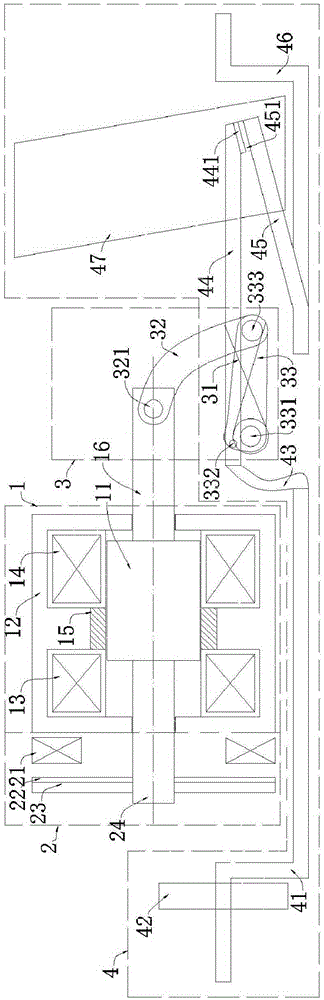
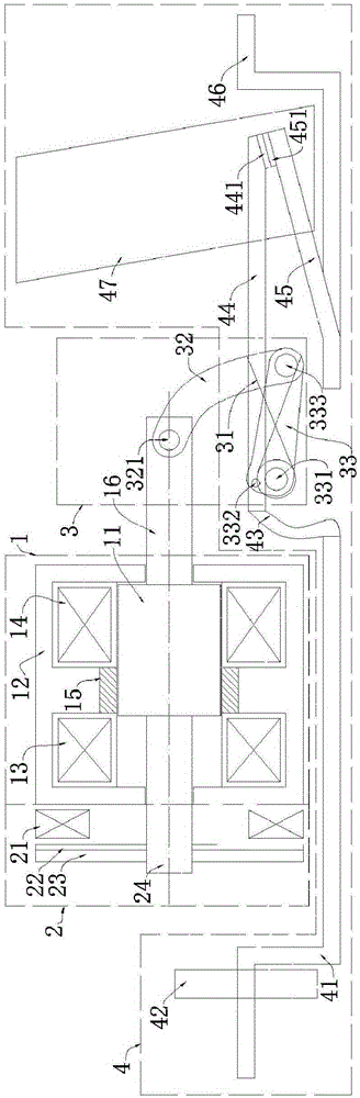
[0025] Example: Reference figure 1 , 2 , 3, a bistable permanent magnet molded case circuit breaker includes an operating mechanism 1, a snap-action mechanism 2, a link mechanism 3, and a main circuit 4; the operating mechanism 1 is connected in series with the snap-action mechanism 2, and The moving mechanism 1 is connected in parallel with the main circuit 4 through the link mechanism 3.

[0026] The operating mechanism 1 of the present invention includes a moving iron core 11, a moving iron core connecting rod 16, a static iron core 12, an opening coil 14, a closing coil 13, and a permanent magnet 15; the moving iron core 11 is fixed on the moving iron connecting rod 16, and Located inside the stationary iron core 12, the opening coil 14 and the closing coil 13 are located between the stationary iron core 12 and the moving iron core 11, and are placed on both sides of the middle pole piece of the stationary iron core 12, and the permanent magnet 15 is located at the end of t...


PUM


Abstract

The invention discloses a bistable permanent magnet moulded case circuit breaker. The bistable permanent magnet moulded case circuit breaker comprises an operating mechanism, a quick acting mechanism, a connecting rod mechanism and a main loop; the operating mechanism is connected with the main loop through the connecting rod mechanism; the operating mechanism comprises a movable iron core, a movable iron core connecting rod, a static iron core, an opening coil, a closing coil and a permanent magnet; the movable iron core is fixed on the movable iron core connecting rod and positioned at the inner side of the static iron core; the opening coil and the closing coil are positioned between the static iron core and the movable iron core and arranged at two sides of a middle pole shoe of the static iron core; simultaneously, the permanent magnet is positioned at the end part of the middle pole shoe of the static iron core and positioned outside the movable iron core; the quick acting mechanism comprises a quick acting winding, a copper disc, an iron disc and an iron disc connecting rod; the quick acting winding is fixed in the front of the outside of the static iron core; the copper disc is fixed on the iron disc; the iron disc is fixed on the iron disc connecting rod; the iron disc connecting rod is fixedly connected with one end of the movable iron core connecting rod; and the copper disc is positioned between the iron disc and the quick acting winding. The bistable permanent magnet moulded case circuit breaker disclosed by the invention has the advantage that opening, closing and quick acting functions are completely controlled electrically.

Description

technical field [0001] The invention relates to a bistable permanent magnet molded case circuit breaker, which can be used for connecting, breaking and protecting the main circuit of high and low voltage electrical equipment. Background technique [0002] At present, the molded case circuit breaker basically adopts the form of a manual operating mechanism plus a release device. The operating mechanism uses spring energy storage to realize the connection, breaking and protection of the main circuit of electrical equipment; the patent number is 201510094877.6 patent "a plastic case "Circuit breaker" realizes the electric control based on the original manual molded case circuit breaker through the energy storage method of the rotating motor. However, the above-mentioned patents and other existing patents that can realize molded case circuit breakers all adopt the form of additional mechanism on the basis of retaining the original operating mechanism. Although this form retains ...

Claims


Application Information

Patent Timeline
Patent Type & Authority Applications(China)
IPC IPC(8): H01H71/32
CPCH01H71/32
Inventor 虞国荣金平江泽南曹兵兵丁高峰种彪
Owner FORETECH ELEC APP JIANGSU CORP
Why Eureka
Try Eureka