
Method for controlling movement of worktable of automatic image measuring instrument

A technology for image measuring instruments and workbenches, which is applied to measuring devices, instruments, and optical devices, etc. It can solve the problems of finding the target position, grasping the speed, direction, and troublesome setting, so as to reduce the number of external control boxes, and the process is smooth and time-saving. , Intuitive effect for the operator

Inactive Publication Date: 2016-03-09
DONGGUAN WEIDA SOFTWARE TECH CO LTD
View PDF7 Cites 1 Cited by
  • Summary
  • Abstract
  • Description
  • Claims
  • Application Information

AI Technical Summary

Problems solved by technology

[0005] In view of this, the present invention aims at the deficiencies existing in the prior art, and its main purpose is to provide a method for controlling the movement of the workbench by an automatic image measuring instrument, which can effectively solve the problem of finding the target position in the traditional method, which is difficult to grasp the speed, direction and troublesome setting. question

Method used


Image

  • Method for controlling movement of worktable of automatic image measuring instrument
  • Method for controlling movement of worktable of automatic image measuring instrument
  • Method for controlling movement of worktable of automatic image measuring instrument

Examples


Embodiment Construction

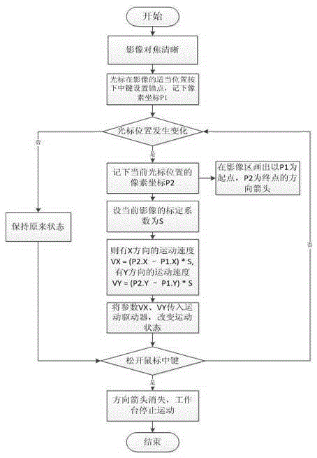
[0028] The present invention discloses a method for controlling the movement of the workbench by an automatic image measuring instrument, please refer to Figure 1 to Figure 8 Shown, it has shown the concrete steps of the preferred embodiment of the present invention:

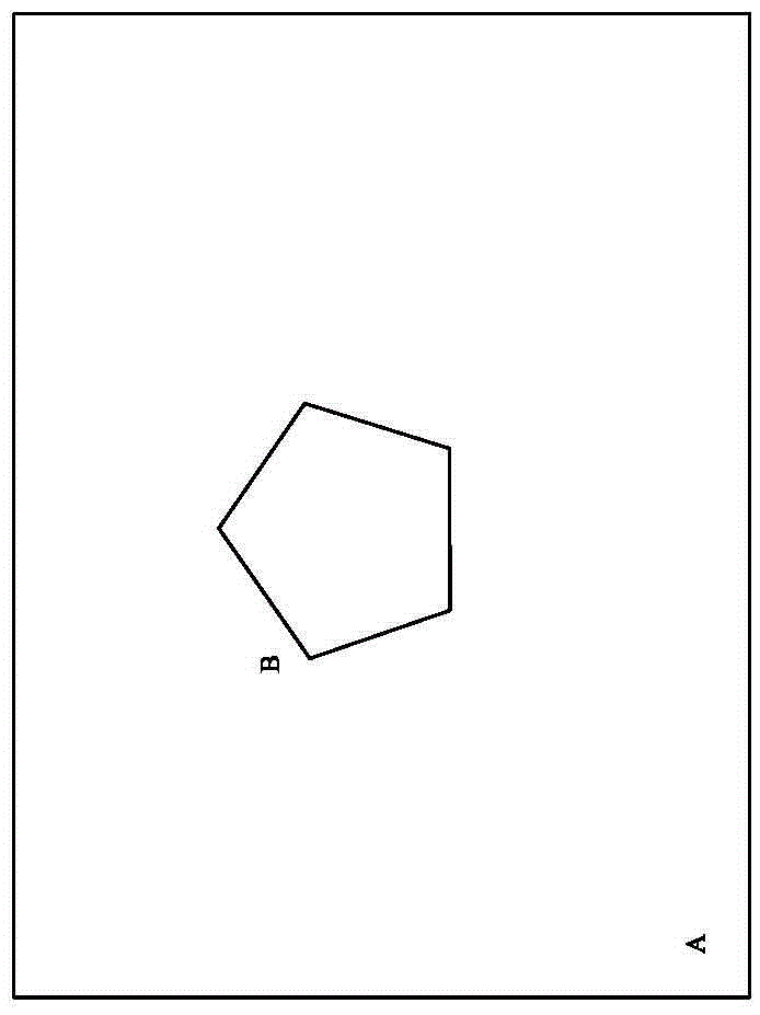
[0029] (1) The image focus is clear. In this embodiment, the image focus is clear manually or automatically, such as figure 2 As shown, the workpiece B to be measured in the image area A is clearly visible.

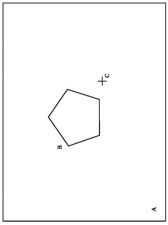
[0030] (2) Put the cursor at the appropriate position in the image area A and press the middle mouse button to set the anchor point C (such as image 3 ), write down the pixel coordinate P1.

[0031] (3) Hold down the middle mouse button and move the cursor, a direction vector arrow D consisting of the anchor point C and the current cursor appears above the image, and the vector arrow changes in real time with the cursor position, forming an effect similar to pulling a rubber band (such as Figure 4 )....


PUM


Abstract

The invention discloses a method for controlling movement of a worktable of an automatic image measuring instrument, which comprises the following steps of (1) performing image focusing for obtaining a clear image; (2) setting an anchor point through pressing down a middle button of a mouse when a cursor is at a proper position of an image area; (3) pressing the middle button of the mouse and moving the cursor, generating a direction vector arrow which is composed of the anchor point and the current cursor above the image, wherein the vector arrow performs real-time change along with position change of the cursor, thereby forming an effect which is similar with an effect in pulling a rubber band; (4) making the worktable move in a manner that the length of the vector arrow after calibration is utilized as speed and the arrow direction is utilized as a movement direction, and changing the movement speed and the movement direction in real time according to the change of the vector arrow; and (5) releasing the middle button of the mouse for stopping movement of the worktable. According to the method of the invention, movement direction and movement speed are defined by means of the direction and the magnitude of the vector arrow generated by pulling, and manual input of the speed is not required. Furthermore the movement speed and the movement direction can be changed in real time, thereby facilitating definition for characteristic positions of a to-be-measured workpiece and improving measurement efficiency.

Description

technical field [0001] The invention relates to the technology in the field of automatic image measuring instruments, in particular to a method for an automatic image measuring instrument to control the movement of a workbench. Background technique [0002] Image measuring instrument, also known as precision image surveying instrument, overcomes the shortcomings of traditional projectors and is a new type of high-precision, high-tech measuring instrument integrating optical, mechanical, electrical, and computer image technologies. The optical microscope performs high-magnification optical magnification imaging on the workpiece to be measured. After the enlarged object image is sent to the computer through the CCD camera system, it can efficiently detect the contours and surface shapes, dimensions, angles and positions of various complex workpieces, especially Microscopic inspection and quality control of precision parts. The measurement data can be directly input into AUTOC...

Claims


Application Information

Patent Timeline
Patent Type & Authority Applications(China)
IPC IPC(8): G01B11/00
CPCG01B11/00
Inventor 吴文聪易三喜巫孟良
Owner DONGGUAN WEIDA SOFTWARE TECH CO LTD
Learn More