
Air deflector structure in main used after flow converging of induced draft fans

A technology of induced draft fan and deflector, which is applied in the field of deflector structure in the main pipe after the confluence of induced draft fans, which can solve the problems of increasing loss along the process, entrained slurry entering, complex flow field, etc., to improve the flow field and reduce the swirl Nest generation, reduce the effect of loss along the way

Active Publication Date: 2016-03-09
JIANGSU FRONTIER ELECTRIC TECH +2
View PDF7 Cites 9 Cited by
  • Summary
  • Abstract
  • Description
  • Claims
  • Application Information

AI Technical Summary

Problems solved by technology

It avoids the complex flow field in the main pipe after confluence in the prior art, and the phenomenon of eddy current increases the loss along the process, and the flue gas flow field at the flue outlet may have a vortex, which will have a bad influence on the desulfurization tower or even entrainment The defect that the slurry enters the main pipe will affect the safe operation of the induced draft fan in severe cases

Method used


Image

  • Air deflector structure in main used after flow converging of induced draft fans
  • Air deflector structure in main used after flow converging of induced draft fans

Examples


Embodiment 1

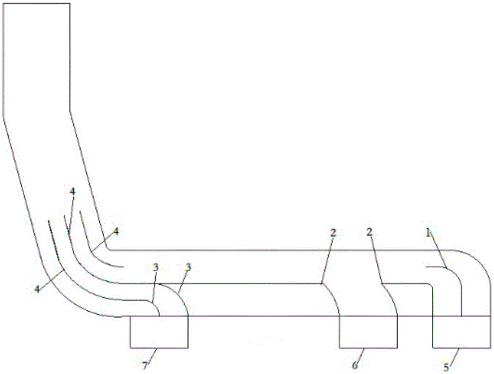
[0016] Such as figure 1 The shown deflector structure device in the main pipe after the confluence of the induced draft fan includes the deflector 1 at the outlet of the first steam-driven induced draft fan, the deflector 3 at the exit of the second steam-driven induced draft fan, the deflector 4 at the corner and Internal baffle 2;

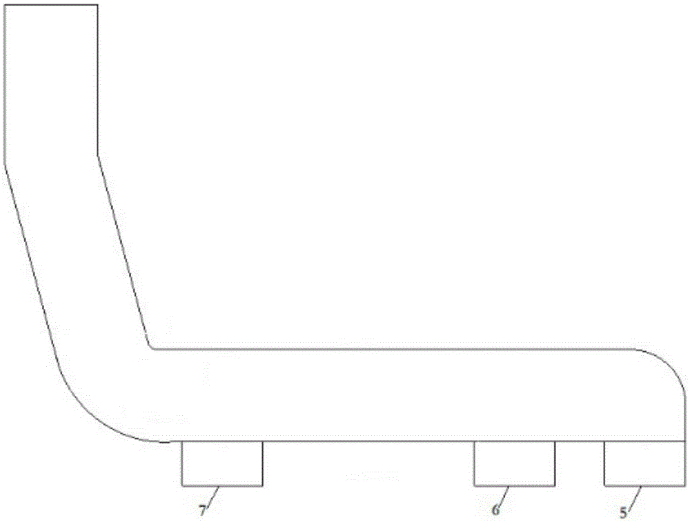
[0017] The outlet 5 of the first steam-driven induced draft fan, the outlet 6 of the electric induced draft fan and the outlet 7 of the second steam-driven induced draft fan are all rectangular air ducts with a cross-section of 7m×6m (7m in the width direction and 6m in the height direction) ); the main pipe air duct is composed of a rectangular channel and an arc-shaped channel, arranged vertically, with a cross-sectional size of 8m×10.2m (8m in the width direction and 10.2m in the height direction);

[0018] The outlet deflector of the first steam-driven induced draft fan is composed of two straight pipe sections and one circular arc section, ...


PUM

PropertyMeasurementUnit
Lengthaaaaaaaaaa

Abstract

An air deflector structure in a main used after flow converging of induced draft fans comprises an air deflector located at an outlet of the first steam-driven induced draft fan, an air deflector located at an outlet of the second steam-driven induced draft fan, an air deflector located at a corner and an internal baffle. All the air deflectors and the baffle are vertically arranged in the main communicated with the outlet of the first steam-driven induced draft fan, an outlet of the electric induced draft fan and the outlet of the second steam-driven induced draft fan in the height direction. The pipeline structure of the main is a wall body structure. The air deflector at the outlet of the first steam-driven induced draft fan, the air deflector at the outlet of the second steam-driven induced draft fan, the air deflector at the corner and the internal baffle are connected with the inner wall of an upper wall body and the inner wall of a bottom wall body of the main. The defects that in the prior art, the flow field in the main after flow converting is complex, and eddies and other phenomena exist, so that linear loss is increased, vortexes which may exist in a smoke flow field of a flue outlet have bad influences on a desulfurizing tower, even slurry is entrained by the vortexes and enters the main, and safe operation of the induced draft fans is affected when the situation is severe are overcome.

Description

technical field [0001] The invention belongs to the technical field of induced draft fans in thermal power plants, and in particular relates to a deflector structure in a main pipe after the confluence of induced draft fans, which plays the role of diverting medium and reducing fluid resistance in the flue. Background technique [0002] At present, as the capacity of coal-fired units increases, the number of induced draft fans increases. Some power plants are equipped with three induced draft fans, one of which is an electric induced draft fan and the other two are steam-driven induced draft fans. During the start-up process, start the electric induced draft fan first, and then incorporate the steam induced induced draft fan. When the second steam induced induced draft fan is incorporated, gradually turn off the electric induced induced draft fan. During normal operation, only two steam-driven induced draft fans operate. During operation, the flue gas flows into the main pi...

Claims


Application Information

Patent Timeline
IPC IPC(8): F23J13/00
CPCF23J13/00
Inventor 马新立邹磊陈有福
Owner JIANGSU FRONTIER ELECTRIC TECH
Learn More