


Quick Research
Generate reliable direction feasibility study reports for your R&D in just a few steps.

Technical Q&A
Discover and master advanced knowledge NOW. Basics, ideas, possibilities, all at once.

Find Solutions
As an expert in R&D theories, this can generate solutions to your technical problems instantly.

Evaluate Feasibility
Analyze your overall solution with one click, know your potential R&D risks in advance.

Monitor Landscape
Get weekly tech updates, stay abreast of the latest tech innovations and key insights.
Reel loading and unloading device
A technology of a driving device and an unwinding mechanism, which is applied in the direction of winding strips, transportation and packaging, and thin material processing, can solve the problems of high labor intensity and low degree of automation, and achieve automation, high degree of automation, and improved automation. The effect of work efficiency
- Summary
- Abstract
- Description
- Claims
- Application Information
AI Technical Summary
Problems solved by technology
Method used
Image

Examples
Embodiment 1
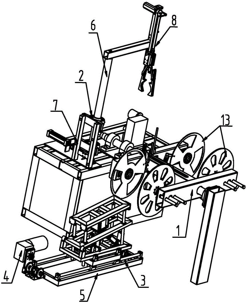
[0032] Such as figure 1 As shown, a coil loading and unloading device includes a rotating arm 1, and the rotating arm 1 is provided with a coil unloading mechanism 3 and a coil loading mechanism 2, and the three are controlled by a PLC control system, which can realize automatic coil unloading And loading work, effectively reducing the labor intensity and improving work efficiency.
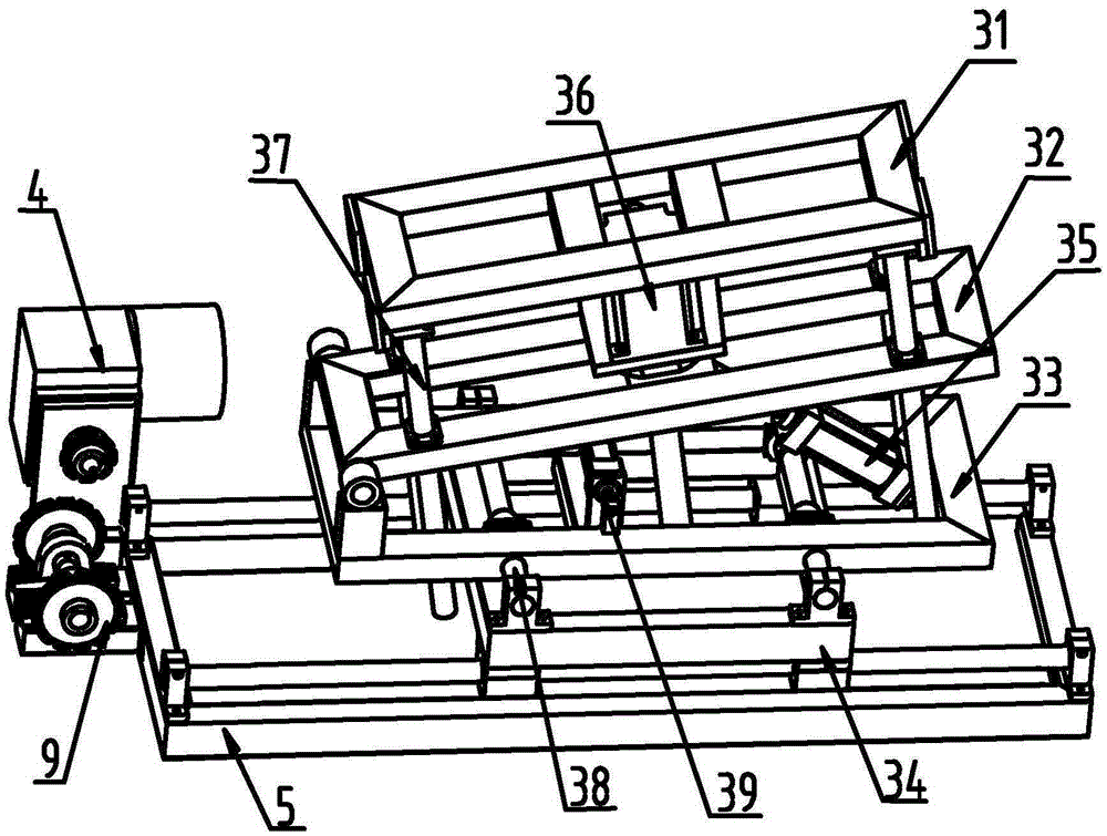
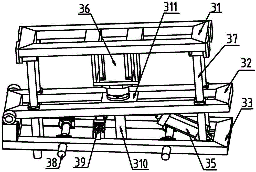
[0033] Such as Figure 1-3 As shown, the unwinding mechanism 3 includes a top layer 31, a middle layer 32, a bottom layer 33, and a base 34 from top to bottom. A driving device 36 and a lead screw 310 are arranged between the top layer 31 and the middle layer 32. The middle layer 32 is provided with a lead screw cover 311 matched with the lead screw 310, and the top layer 31, the middle layer 32 and the bottom layer 33 are provided with telescopic rods 37 inside, and the telescopic rods 37 cooperate with the lead screw 310 and the lead screw cover 311. Play a guiding role in the moving process, ...
Embodiment 2
[0037] Such as figure 1 , 7 As shown, the rotating arm 1 is provided with a reel assembly 13, and the reel assembly 13 is respectively provided with a positioning member 11, a tapered slot 14 and a cylinder three 12, and the positioning member 11 is used to fix an empty roll disc, the cylinder 12 is used to change the distance of the reel assembly 13, and the tapered slot 14 is helpful to successfully complete the installation operation of the empty reel.
[0038] Such as figure 1 , 5 , 6 and 7, the loading mechanism 2 includes a rotating device 7 and a clamping device 8 connected by the connecting arm 6, the rotating device 7 includes cylinder four 71 and slideway three 72, the cylinder four 71 and One end of the slideway three 72 is fixedly connected, the cylinder four 71 can drive the slideway three 72 to move, the bottom of the connecting arm 6 is provided with a gear two 74, and the slideway three 72 is provided with teeth matched with the gear two 74 Bar 73, during t...
Embodiment 3
[0042] Such as Figure 1-7 As shown, when working specifically:
[0043] 1. The driving device 3 81 drives the synchronous pulley 82 and the synchronous belt 83 to rotate, and then drives the moving rod 84 and the clamping part to move down, the clamping part reaches the empty reel storage place, and the cylinder 5 86 is in the In the elongated state, the crank set 87 is driven to complete the operation of clamping the empty reel;
[0044] 2. The PLC control system sends a reverse command to the driving device 3 81 to urge the moving rod 84 and the clamping part to move upward. At the same time, the PLC control system sends a work command to the cylinder 4 71 to urge the slideway The third 72 moves, drives the second gear 74 and the gripping device 8 to rotate, and the connecting arm 6 rotates to the limit device 75. At this time, the empty pipe reel is positioned above the reel assembly 13, and the PLC control system Send a stop command to the cylinder four 71, and send a c...
PUM
 Abstract
Description
Claims
Application Information
 - R&D Engineer
- R&D Manager
- IP Professional
- Industry Leading Data Capabilities
- Powerful AI technology
- Patent DNA Extraction
Browse by: Latest US Patents, China's latest patents, Technical Efficacy Thesaurus, Application Domain, Technology Topic, Popular Technical Reports.
© 2024 PatSnap. All rights reserved.Legal|Privacy policy|Modern Slavery Act Transparency Statement|Sitemap|About US| Contact US: help@patsnap.com