Unilateral arm-folding type spiral material leveling machine
A technology of leveling machine and screw, which is applied in the field of unilateral folding arm type screw leveling machine. Good effect, strong pushing ability and convenient operation
- Summary
- Abstract
- Description
- Claims
- Application Information
AI Technical Summary
Problems solved by technology
Method used
Image
Examples
Embodiment 1
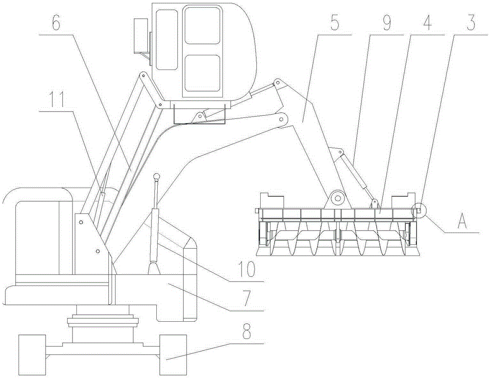
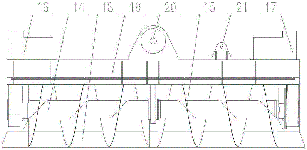
[0036] Such as figure 1 , figure 2 As shown, the unilateral folding arm type spiral flat material machine 1 includes the anti-deviation device 3, the spiral flat material pushing mechanism 4, the boom system 5, the driver's cab device 6, the rotary mechanism 7, the traveling mechanism 8, the screw adjustment cylinder 9, Boom oil cylinder 10, cab lifting oil cylinder 11. The sensor connection bracket 12 of the anti-deflection device 3 is affixed to both sides of the spiral bracket 19 of the spiral flat material pushing mechanism 4; Point 27 is connected; the head of the spiral adjustment cylinder 9 is connected with the screw adjustment cylinder connection seat 21 of the spiral flat material pushing mechanism 4, and the tail of the spiral adjustment cylinder 9 is connected with the screw adjustment cylinder support seat 32 of the boom system 5 , the telescopic movement of the screw adjustment oil cylinder 9 can keep the spiral flat material pushing mechanism 4 always at a le...
Embodiment 2
[0044] It includes anti-deflection device 3, spiral flat material pushing mechanism 4, boom system 5, driver's cab device 6, slewing mechanism 7, traveling mechanism 8, screw adjustment cylinder 9, boom cylinder 10, and cab lifting cylinder 11. Except that running mechanism 8, all the other structures are with embodiment one.
[0045] Such as Figure 13 , Figure 14 Shown, running gear 8 adopts tire type running gear 53, and tire type running gear 53 comprises walking tire 54, wheel fixed end beam 55, wheel support 56, slewing bearing 52, wheel steering gear 57, wheel steering drive means 58. The wheel bracket (56) is an H-shaped metal member, and the beams on both sides are arranged symmetrically along the center line of the wheel bracket (56) in the longitudinal direction. The lower end surface of the device 57 is connected with the upper end surface of the fixed end beam 55 of the wheel, and the running tires 54 are arranged below the fixed end beam 55 of the wheel. The f...
PUM
 Abstract
Description
Claims
Application Information
 - R&D
- Intellectual Property
- Life Sciences
- Materials
- Tech Scout
- Unparalleled Data Quality
- Higher Quality Content
- 60% Fewer Hallucinations
Browse by: Latest US Patents, China's latest patents, Technical Efficacy Thesaurus, Application Domain, Technology Topic, Popular Technical Reports.
© 2025 PatSnap. All rights reserved.Legal|Privacy policy|Modern Slavery Act Transparency Statement|Sitemap|About US| Contact US: help@patsnap.com


