Clamping part for automatic pipe bending machine

A technology of clamping parts and pipe bending machines, which is applied in the field of clamping parts for automatic pipe bending machines, can solve problems affecting product qualification rate, high labor cost, lack of flexibility, etc., and achieve simple structure, low labor cost, Simple and fast effect

Active Publication Date: 2017-10-17
山东欧盛建材有限公司
View PDF3 Cites 0 Cited by
  • Summary
  • Abstract
  • Description
  • Claims
  • Application Information

AI Technical Summary

Problems solved by technology

In the actual use process, the stability of the clamping parts installation is directly related to the accuracy of the bending angle of the product when the pipe bending machine performs the pipe bending operation, which directly affects the product qualification rate, and then the current overtime fixed pair is Using bolts to lock directly, in actual use, lack of flexibility, and the screw hole precision is not enough, it will directly produce a large number of waste parts, and at the same time, most of the current clamping parts are manually operated, which is time-consuming, labor-intensive, labor-intensive, and efficient It is low and requires high technology and proficiency of pipe bending personnel, high labor cost and large labor force

Method used


Image

  • Clamping part for automatic pipe bending machine
  • Clamping part for automatic pipe bending machine
  • Clamping part for automatic pipe bending machine

Examples


Embodiment Construction

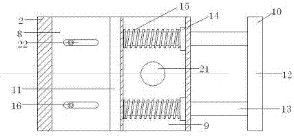
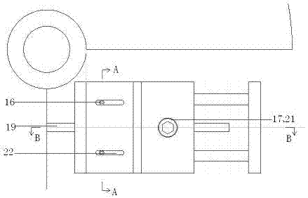
[0019] A clamping part for a fully automatic pipe bender, characterized in that the clamping part 2 includes a clamping part 8, a spring part 9 and a telescopic plate 10, and the telescopic plate 10 includes a splint 11 located at the clamping part, The pressing plate 12 and the spring telescopic rod 13 that are positioned at one side of the spring part 9, the number of the spring telescopic 13 rods are 2, the two ends of which are respectively connected to the splint 11 and the pressing plate 12, and the middle of the spring telescopic rod 13 is provided with a bump 14, the said The bump 14 is located in the spring part 9, and the spring part 9 is provided with a spring 15. The number of the springs 15 is 2, which are respectively fitted on the 2 spring telescopic rods 13, and one end of the spring 15 is pressed against the bump 14, the other end is pressed against the inner wall of the spring part 9;

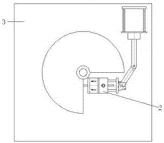
[0020] The clamping member 2 is detachably connected to the panel 3 of th...


PUM


Abstract

The invention relates to a clamping part for a fully automatic pipe bending machine. The clamping part includes a clamping part, a spring part and an expansion plate. Through three-point positioning, the accuracy of the installation position of the clamping part is ensured. The waist-shaped hole and the strip-shaped positioning groove are used together, and the gap between the guide strip and the guide strip groove can be adjusted flexibly on the strip-shaped direction of the positioning groove. The installation process of the clamping piece is very simple. , extremely convenient, in summary, the present invention has the characteristics of simple installation, simple structure, flexible adjustment, high installation precision, simple and fast operation, small labor force, low labor cost and high pipe bending efficiency.

Description

technical field [0001] The invention relates to an assembly component of a pipe bending machine, in particular to a clamping part for a fully automatic pipe bending machine. Background technique [0002] Pipe bending machines can be roughly divided into CNC pipe bending machines, hydraulic pipe bending machines and so on. It is mainly used in electric power construction, highway and railway construction, pipeline laying and repairing in boilers, bridges, ships, furniture, decoration, etc. It has the advantages of multiple functions, reasonable structure, and simple operation. In the actual use process, the stability of the clamping parts installation is directly related to the accuracy of the bending angle of the product when the pipe bending machine performs the pipe bending operation, which directly affects the product qualification rate, and then the current overtime fixed pair is Using bolts to lock directly, in actual use, lack of flexibility, and the screw hole precis...

Claims


Application Information

Patent Timeline
Patent Type & Authority Patents(China)
IPC IPC(8): B21D7/16
Inventor 程春良郭宏兵郭澍程永胜
Owner 山东欧盛建材有限公司
Why Eureka
Try Eureka