Connectors and their accessories

A technology for connectors and accessories, which is applied in the parts of connection devices, connections, and devices for relieving stress at wire connections. It can solve the problems of optical signal transmission attenuation, affecting the tensile performance of connectors, and bending, etc. Tensile strength, avoid bending, ensure the effect of stability and reliability

Active Publication Date: 2018-07-06
CHINA AVIATION OPTICAL-ELECTRICAL TECH CO LTD
View PDF5 Cites 0 Cited by
  • Summary
  • Abstract
  • Description
  • Claims
  • Application Information

AI Technical Summary

Problems solved by technology

[0004] When this kind of optical fiber connector seals between the main cable and the sleeve through the tail sealing structure, the lock nut presses the retaining ring to deform the rubber sleeve, and the left end of the rubber sleeve radially tightens and hugs the main cable, locking There is a lot of friction between the nut and the retaining ring, between the retaining ring and the rubber sleeve, and between the rubber sleeve and the main cable. When you continue to turn the lock nut to move to the left, it will drive the main cable to move to the left. , so that the branch optical cable located in the sleeve will be bent, causing the transmission attenuation of the optical signal, and the adhesive sleeve will move to the left with the main cable and will not fit with the adhesive sleeve stop surface of the sleeve, which will also affect the connection Tensile properties of the device

Method used


Image

  • Connectors and their accessories
  • Connectors and their accessories
  • Connectors and their accessories

Examples


Embodiment 1

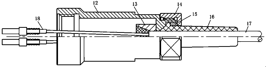
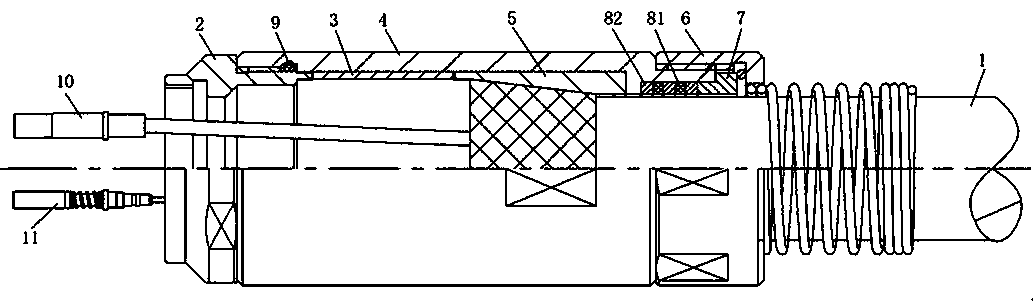
[0025] Embodiment 1 of the connector of the present invention: includes a connector accessory and a plug, wherein the structure of the connector accessory is as follows Figure 2-7 As shown, it includes a sleeve 4 extending left and right. The left end of the sleeve 4 is threaded with an adapter sleeve 2, and the right end is threaded with a tail sealing structure. The main cable 1 passes through the tail sealing structure, the sleeve and the adapter sleeve from right to left. The tail sealing structure is used to ensure the seal between the right end of the sleeve and the main cable, and the adapter sleeve 2 is used to Adapted socket connector connection, the sleeve is provided with an adhesive sleeve 5, the main cable 1 and the adhesive sleeve 5 are bonded and fixed, and there is also a sleeve in the sleeve for blocking the adhesive sleeve in the right direction. The stop surface of the adhesive sleeve to prevent the adhesive sleeve and the main cable from coming out of the ...

Embodiment 2

[0029] Embodiment 2 of the connector of the present invention: the difference from Embodiment 1 lies in that the axial limiting sleeve and the bonding sleeve are integrated.

Embodiment 3

[0030] Embodiment 3 of the connector of the present invention: the difference from Embodiment 1 lies in that the axial limiting sleeve and the adhesive sleeve are arranged separately and fixed by bonding.

[0031] Embodiment 4 of the connector of the present invention: the difference from Embodiment 1 is that the plug-in structure is a protrusion extending left and right provided on the inner peripheral surface of the adapter sleeve and a protrusion provided on the axial limit sleeve. The chute extending left and right, when the sleeve is connected to the adapter sleeve, the chute on the axial limit sleeve and the protrusion on the adapter sleeve slide and cooperate to realize the circumferential direction of the axial limit sleeve and the adapter sleeve. stop turning.

[0032] Embodiment 5 of the connector of the present invention: the difference from Embodiment 1 lies in that the adapter sleeve and the sleeve are connected by a hook structure.

[0033] Embodiment 6 of the c...


PUM


Abstract

The invention provides a connector and a connector accessory thereof. The connector comprises a plug, a sleeve and a tail sealing structure. The sleeve is internally provided with an adhesive sleeve. The sleeve is provided with an adhesive sleeve stop surface which is used for stopping and limiting the adhesive sleeve in a rightward direction. The connector also comprises a reducing sleeve which is connected at the left end of the sleeve and used for being connected with an adaptive socket. The adhesive sleeve is provided with an axial limiting sleeve. The axial limiting sleeve is provided with a stop matching surface which is used for being matched with the adapter sleeve in a stopping way so as to stop axial movement of the adhesive sleeve relative to the adaptive sleeve when the tail sealing structure is rotatably connected on the sleeve. According to the connector, the adhesive sleeve and the axial limiting sleeve are pressed on the adapter sleeve by the sleeve and axial movement of the adhesive sleeve and the axial limiting sleeve is ensured not to occur so that a main cable does not axially and circumferentially move under the frictional force of a tail connecting structure when the tail sealing structure is connected and use reliability of the connector can be guaranteed.

Description

technical field [0001] The invention relates to a photoelectric connection element, in particular to a connector and its accessories. Background technique [0002] With the rapid development of optoelectronic technology, the connector, as an important part of the transmission and transfer of optoelectronic signals, plays a very important role in the optoelectronic transmission system, and whether the sealing performance of the connector is good or not has a great impact on the transmission quality of optoelectronic signals. have a great impact. [0003] The sealing of general optical fiber connectors is realized by corresponding connector accessories. Common fiber optic connector accessories and connector structures are as follows: figure 1 As shown, it includes a plug 18, a main cable 17, a sleeve 12, an adhesive sleeve 13 and a rubber sleeve 16. The right end of the sleeve is also provided with a tail sealing structure for sealing between the main cable and the sleeve. ...

Claims


Application Information

Patent Timeline
Patent Type & Authority Patents(China)
IPC IPC(8): H01R13/502H01R13/512H01R13/52H01R13/58G02B6/38
CPCG02B6/3849G02B6/3873H01R13/502H01R13/512H01R13/5205H01R13/5812
Inventor 张海生方尚杰
Owner CHINA AVIATION OPTICAL-ELECTRICAL TECH CO LTD
Why Eureka
Try Eureka