
Side-light type light-emitting module

A light-emitting module and side-light technology, which is applied in the field of side-light light-emitting modules, can solve problems such as cost and power loss, optical dark areas are not obvious, and the gap between light sources is too large

Inactive Publication Date: 2016-03-02
EPOCH CHEMTRONICS
View PDF5 Cites 1 Cited by
  • Summary
  • Abstract
  • Description
  • Claims
  • Application Information

AI Technical Summary

Problems solved by technology

[0006] By setting a plurality of LED strip light sources, although the problem of optical dark areas can be solved, another problem will be derived, that is, when the number of light sources is too small, the gap between the light sources will be reduced. If the gap between multiple light sources is too large, the obvious problem of the optical dark area cannot be perfectly solved. However, if the light distribution is uniform and the optical dark area is not obvious, it is necessary to make the gap between multiple light sources The shortening of the gap produces a large number of light-emitting diodes in the strip light source, resulting in a large amount of cost and power loss
[0007] The reason is that the traditional side-light light-emitting module needs to be equipped with more light-emitting diodes to solve the problem of optical dark areas. In view of this, the inventor designed a way to use reflection to provide a uniform surface light source with a small number of light sources. , which is assisted by many years of manufacturing and design experience and knowledge in related fields, and a newer research and development improvement for the existing edge-lit light-emitting module, in order to exert its higher practical benefits

Method used


Image

  • Side-light type light-emitting module
  • Side-light type light-emitting module
  • Side-light type light-emitting module

Examples


Embodiment Construction

[0046] In order to make the structural features of the present invention and the achieved effects have a further understanding and recognition, preferred embodiments and detailed descriptions are specially used, which are described as follows:

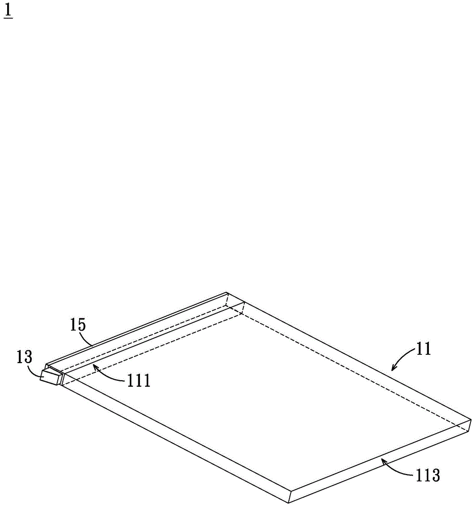
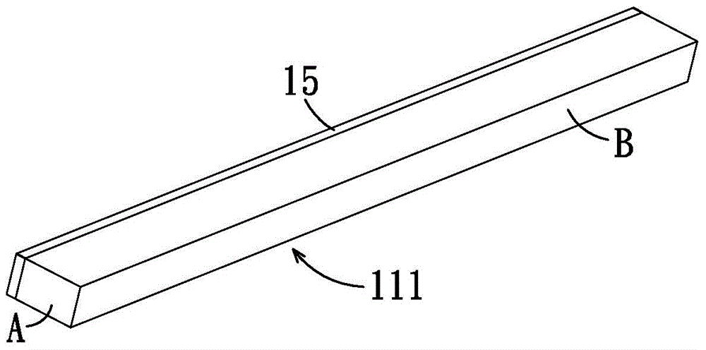
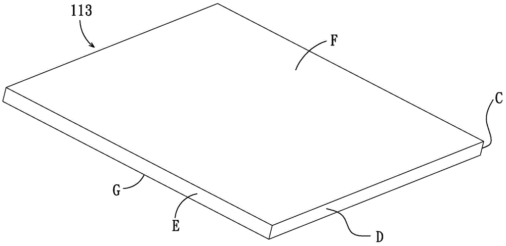
[0047] The present invention relates to a side-light light-emitting module, first please refer to Figure 1A to Figure 1C Figure, which is an exploded view of the structure of the first embodiment of the present invention, as shown in the figure, the present invention provides a side-light light-emitting module, which includes a first light-emitting unit 13, a light guide plate 11, and at least one first A reflector 15.

[0048] The first light emitting unit 13 is a light emitting diode, and the first light emitting unit 13 can be freely replaced according to user requirements.

[0049] The light guide plate 11 is provided with a first space 111 and a second space 113, a first light incident surface A of the first space 111 is provide...


PUM


Abstract

The invention relates to a side-light type light-emitting module which comprises a light guide plate, a first light-emitting unit and reflecting pieces. After penetrating at least the first reflecting piece, light emitted by the first light-emitting unit is uniformly guided to the light-exiting face of the light guide plate, and the side-light type light-emitting module can be provided with one or more light-exiting faces through the design of multiple dots additionally arranged on the light guide plate and the second reflecting piece.

Description

technical field [0001] The invention relates to a side-light light emitting module, in particular to a side light light-emitting module using secondary optics. Background technique [0002] Generally speaking, the light-emitting diode (LED, Light-Emitting-Diode) light emitting method includes point light source and surface light source. The point light source is a light source idealized as a particle that emits light in all directions, and the surface light source consists of the entire surface of the light-emitting area. Gives even light. Compared with the LED point light source, the LED surface light source is a flood light, so the light angle is larger, and it is less likely to produce black shadows or double shadows. There is no glare, and the light is uniform and soft without hurting the eyes. Although there is also a way to make the overall light soft and uniform through the design of the lampshade in the point light source, but through this method, part of the light ...

Claims


Application Information

Patent Timeline
IPC IPC(8): F21S2/00F21V8/00F21V7/00F21Y101/02
Inventor 谢锦坤简俊杰
Owner EPOCH CHEMTRONICS
Learn More