
Reversible electromagnetic clutch

An electromagnetic clutch and electromagnet technology, applied in the clutch field, can solve the problems of cumbersome operation process and reduced work efficiency, etc.

Pending Publication Date: 2016-03-02
CHONGQING CHENGSHUO TECH
View PDF9 Cites 2 Cited by
  • Summary
  • Abstract
  • Description
  • Claims
  • Application Information

AI Technical Summary

Problems solved by technology

[0003] Traditional clutches rely on the combination and separation of two halves of the clutch plate to achieve power transmission and interruption. There are many types of clutches, mainly including mechanical clutches, pneumatic clutches, hydraulic clutches, electromagnetic clutches, etc. When it remains unchanged, the running direction of the driven shaft cannot be changed. If it is necessary to change the running direction of the driven shaft, the running direction of the driving shaft must be changed. Therefore, in some occasions where the driven shaft needs to change the direction continuously , it is necessary to change the running direction of the drive shaft continuously, which will make the whole operation process very cumbersome and greatly reduce the work efficiency

Method used


Image

  • Reversible electromagnetic clutch

Examples


Embodiment Construction

[0011] The present invention will be described in further detail below by means of specific embodiments:

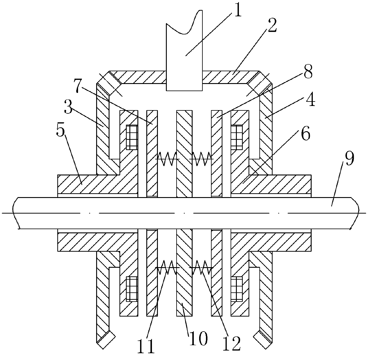
[0012] The reference signs in the drawings of the description include: drive shaft 1, main bevel gear 2, first bevel gear 3, second bevel gear 4, first electromagnet 5, second electromagnet 6, first pressure ring 7, the first bevel gear Second pressure ring 8, driven shaft 9, main pressure ring 10, first extension spring 11, second extension spring 12.

[0013] The embodiment is basically as attached figure 1 Shown: the reversible electromagnetic clutch, including the drive shaft 1, the shaft extension end of the drive shaft 1 is covered with the main bevel gear 2, the drive shaft 1 and the main bevel gear 2 are installed and fixed by interference fit, and there is a The first bevel gear 3 is provided with a second bevel gear 4 on the right side of the main bevel gear 2 .

[0014] The left side of the first electromagnet 5 is provided with a first protrusion, and the fi...


PUM


Abstract

The invention discloses a reversible electromagnetic clutch. The reversible electromagnetic clutch comprises a driving shaft, a driven shaft, a first electromagnet and a second electromagnet, wherein a main bevel gear is arranged on the driving shaft; two sides of the main bevel gear are respectively meshed with a first bevel gear and a second bevel gear; the first bevel gear is sleeved on the first electromagnet; the second bevel gear is sleeved on the second electromagnet; a first compression ring, a main compression ring and a second compression ring are also successively arranged between the first electromagnet and the second electromagnet on the driven shaft; at least one first tension spring is arranged between the first compression ring and the main compression ring; at least one second tension spring is arranged between the second compression ring and the main compression ring. The reversible electromagnetic clutch has the beneficial effect that the driven shaft can operate in different directions according to load conditions under the condition that the rotation direction of the driving shaft is not changed; meanwhile, the reversible electromagnetic clutch is simple in structure and convenient to operate.

Description

technical field [0001] The invention relates to the field of clutches, in particular to a reversible electromagnetic clutch. Background technique [0002] A clutch is a device that realizes the transmission of motion and power between the active and driven parts on the coaxial line and has the function of engaging or separating. Engage or disengage. [0003] Traditional clutches rely on the combination and separation of two halves of the clutch plate to achieve power transmission and interruption. There are many types of clutches, mainly including mechanical clutches, pneumatic clutches, hydraulic clutches, electromagnetic clutches, etc. When it remains unchanged, the running direction of the driven shaft cannot be changed. If it is necessary to change the running direction of the driven shaft, the running direction of the driving shaft must be changed. Therefore, in some occasions where the driven shaft needs to change the direction continuously , then it is necessary to ...

Claims


Application Information

Patent Timeline
Patent Type & Authority Applications(China)
IPC IPC(8): F16D27/04F16D27/14
Inventor 陈佳英
Owner CHONGQING CHENGSHUO TECH
Learn More