Fan control circuit

A fan control and circuit technology, applied in pump control, non-variable pumps, machines/engines, etc., can solve problems such as temperature sensitivity, different temperature resistance values, and inability to meet chip heat dissipation requirements

Inactive Publication Date: 2016-03-02
HONG FU JIN PRECISION IND (SHENZHEN) CO LTD +1
View PDF6 Cites 7 Cited by
  • Summary
  • Abstract
  • Description
  • Claims
  • Application Information

AI Technical Summary

Problems solved by technology

In the existing fan control circuit design, the processor usually receives a single temperature detection signal and adjusts the fan speed according to the preset software algorithm. How...

Method used


Image

  • Fan control circuit
  • Fan control circuit

Examples


Embodiment Construction

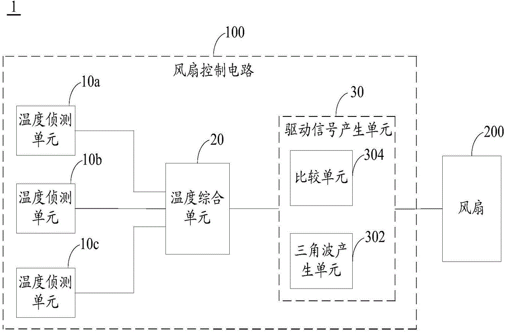
[0032] figure 1 It is a block diagram of the fan control circuit 100 in an embodiment of the present invention. In this embodiment, the electronic device 1 includes a plurality of heating elements (not shown in the figure), a fan control circuit 100 and a fan 200, wherein the fan control circuit 100 is used to control the rotation of the fan 200 to achieve active heat dissipation, thereby ensuring that the electronic Device 1 does not overheat during operation. The fan control circuit 100 includes a plurality of temperature detection units 10a, 10b, 10c (in this embodiment, only three are used as an example, but not limited to three, and may include less than or more than three temperature detection units ), the temperature integration unit 20 and the drive signal generation unit 30. Each temperature detection unit 10a, 10b, 10c detects the temperature of a heating element and outputs a corresponding temperature detection signal. In this embodiment, the plurality of heating...


PUM


Abstract

A fan control circuit comprises a plurality of temperature detection units, a temperature comprehensive unit and a drive signal generation unit. The temperature detection units are used for detecting running temperatures of multiple heating elements in an electronic device respectively so as to correspondingly output multiple temperature detection signals. The temperature comprehensive unit is electrically connected to the multiple temperature detection units and used for working out an average-value temperature signal according to the temperature detection signals and multiple corresponding preset weighted values. The drive signal generation unit is electrically connected to the temperature comprehensive unit and used for generating a drive signal according to the average-value temperature signal output by the temperature comprehensive unit so as to drive a fan. According to the fan control circuit, the detected temperatures are worked out through the multiple temperature detection units and the corresponding weighted values, the duty ratio of the drive signal of the fan is regulated according to the detected temperatures, and therefore the rotating speed of the fan is regulated in real time, and electric power is saved.

Description

technical field [0001] The invention relates to the field of fans in electronic equipment, in particular to a fan control circuit in electronic equipment. Background technique [0002] In some electronic devices that generate a lot of heat, fans are usually designed to actively dissipate heat. At the same time, the fan needs a fan control circuit to adjust the fan speed according to the temperature change in the electronic device. In the existing fan control circuit design, the processor usually receives a single temperature detection signal and adjusts the fan speed according to the preset software algorithm. However, the sensitivity and temperature resistance of each chip in the electronic device are not the same. The temperature detection of the chip cannot meet the heat dissipation requirements of each chip. Therefore, designing a fan control circuit capable of performing weighted temperature detection calculations according to the importance of each chip in the electro...

Claims


Application Information

Patent Timeline
IPC IPC(8): F04D27/00
Inventor 陈钰家
Owner HONG FU JIN PRECISION IND (SHENZHEN) CO LTD
Why Eureka
Try Eureka