
A horizontal loop guide roller device

A technology of guide roller device and horizontal looper, which is applied in the direction of bending workpieces, metal processing equipment, metal rolling, etc., can solve the problems of unqualified cold heading performance, damage of bearings and circlips, batch quality accidents, etc. The effect of stacking steel accidents, reducing wear, and improving the operating rate of the rolling mill

Active Publication Date: 2018-04-24
MAANSHAN IRON & STEEL CO LTD
View PDF6 Cites 0 Cited by
  • Summary
  • Abstract
  • Description
  • Claims
  • Application Information

AI Technical Summary

Problems solved by technology

The exit guide roller of the existing horizontal looper device is composed of a guide roller with a platform and two flat rollers. The roller surface of the guide roller with a platform has steps to prevent the upward movement of the rolled piece, but its internal structure is the same as that of the flat roller. High-speed wire The rolling piece moves in an arc shape after the horizontal looper is set up. Under the action of the upward force of the rolling piece, the bearing and the retaining spring of the belt table guide roller often suffer damage. Scratches, affecting product quality, and even lead rollers fall off and cause stacking accidents
For the production of high value-added products such as annealing-free, simplified annealing and non-quenched and tempered steel with high cold heading performance, the shape of the bar is very demanding during the rolling process, and a small scratch of 0.05mm on the finished product may cause cold heading of the product If the performance is unqualified, if there is a scratch greater than 0.2mm on the strip in the middle rolling area, it is reflected in the finished product as intermittent folding, which is not easy to find with the naked eye, but the rolled product may be a waste product, which can easily cause batch quality accidents

Method used


Image

  • A horizontal loop guide roller device

Examples


Embodiment Construction

[0023] The specific embodiment of the present invention will be described in further detail by describing the embodiments below with reference to the accompanying drawings, the purpose is to help those skilled in the art to have a more complete, accurate and in-depth understanding of the concept and technical solutions of the present invention, and contribute to its implementation.

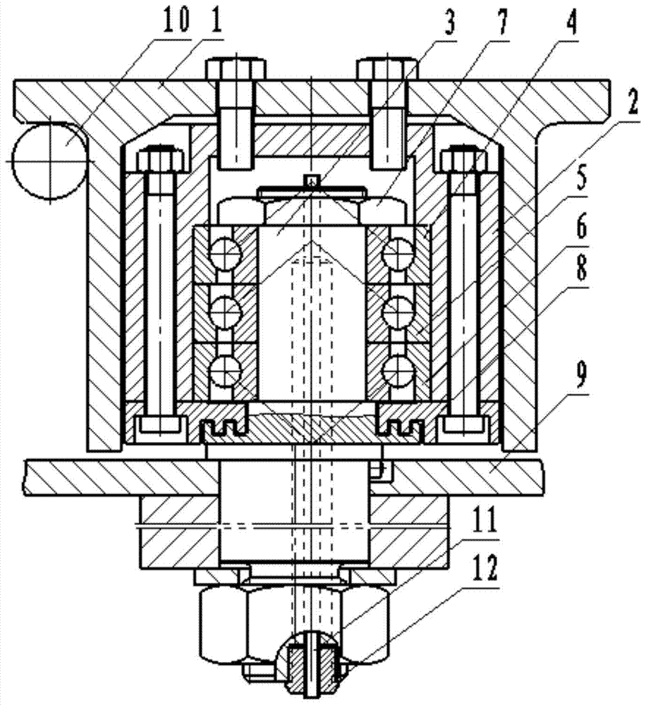
[0024] Such as figure 1 As shown, the present invention specifically relates to a horizontal looper guide roller device, comprising a looper table 9, a belt table guide roller 1 and a bush 2 arranged in the belt table guide roller 1, and the guide roller device also includes an eccentric shaft 3, The bearing set and the locking device used to lock the two ends of the bearing set. The eccentric shaft 3 includes the first shaft part, the connecting part and the second shaft part arranged in the bushing in sequence. The belt table guide roller 1 passes through the first The shaft part is connected t...


PUM


Abstract

The invention discloses a horizontal loop guide roller device which comprises a loop table, a guide roller with a table and a lining arranged in the guide roller with the table. The guide roller device further comprises an eccentric shaft, a bearing set and locking devices used for locking the two ends of the bearing set. The eccentric shaft comprises a first shaft part and a second shaft part arranged in the lining. The guide roller with the table is connected with the loop table through the first shaft part. The bearing set is arranged between the second shaft part and the lining and bears axial loads in the axial directions of the two ends of the bearing set by means of the series-connection arrangement and back-to-back arrangement between bearings. According to the guide roller device, the loop bearings and clamping springs can be prevented from being damaged, the situation that because the guide roller plays, a rolled piece is scratched by an outlet guide groove is avoided, the steel piling accidents caused by falling-off of the guide roller are eradicated, abrasion to the loop outlet guide groove and an inlet guide of a rolling mill is reduced, the product quality is improved, and rolling cost is reduced.

Description

technical field [0001] The invention belongs to the technical field of metal rolling equipment, and in particular relates to a horizontal loop guide roller device. Background technique [0002] Between the high-speed wire roughing mill and the pre-finishing mill, in order to realize tension-free rolling, a horizontal looper device is installed to adjust the speed of the upstream rolling mill, so as to ensure that the volume flow per second of the front and rear racks is equal. The exit guide roller of the existing horizontal looper device is composed of a guide roller with a platform and two flat rollers. The roller surface of the guide roller with a platform has steps to prevent the upward movement of the rolled piece, but its internal structure is the same as that of the flat roller. High-speed wire The rolling piece moves in an arc shape after the horizontal looper is set up. Under the action of the upward force of the rolling piece, the bearing and the retaining spring o...

Claims


Application Information

Patent Timeline
Patent Type & Authority Patents(China)
IPC IPC(8): B21B41/00
CPCB21B41/00
Inventor 刘朝彤宋强陈晓明王金来张本练孙山
Owner MAANSHAN IRON & STEEL CO LTD
Learn More