
Footstool frame

A technology for a footstool and a footrest is applied in the field of footstool brackets, which can solve the problems of large floor space and increase the difficulty of handling, and achieve the effects of easy transportation, simple structure and good structure firmness.

Inactive Publication Date: 2016-03-02
王剑
View PDF6 Cites 0 Cited by
  • Summary
  • Abstract
  • Description
  • Claims
  • Application Information

AI Technical Summary

Problems solved by technology

However, in the process of handling and storage, it occupies a large area, which increases the difficulty of handling.

Method used


Image

  • Footstool frame

Examples


Embodiment 1

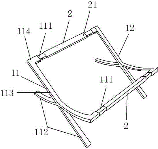
[0017] A footstool stand, as attached figure 1 As shown, it can be made of metal, plastic or wood, and the present embodiment is made of stainless steel, including two opposite supporting frames forming a flat footrest surface on the upper part and a connecting body 2 connecting the supporting frames. The support frame includes a first support body 11 and a second support body 12. The first and second support bodies all have a transition portion 113 between the connection portion 111 and the support portion 112. The transition portion 113 of the first support body 11 is connected to the second support body. The included angle between the transition portions 113 of the support body 12 is 90-150°, which is 120° in this embodiment; the first support body 11 and the second support body 12 are cross-connected on their respective transition portions 113, and also It can be designed such that the transition portion 113 of the two supporting bodies is integrated at the middle position...

Embodiment 2

[0019] A footstool bracket, which can be made of metal, plastic, or wood. This embodiment is made of wood, and includes two opposing support frames forming a flat footrest surface on the upper part and a connecting body 2 connecting the support frames. The support frame includes a first support body 11 and a second support body 12. The first and second support bodies all have a transition portion 113 between the connection portion 111 and the support portion 112. The transition portion 113 of the first support body 11 is connected to the second support body. The included angle between the transition portions 113 of the support body 12 is 90-150°, which is 120° in this embodiment; the first support body 11 and the second support body 12 are cross-connected on their respective transition portions 113, and also It can be designed such that the transition portion 113 of the two supporting bodies is integrated at the middle position. Both ends of the connecting body 2 are provided ...


PUM


Abstract

The invention relates to a footstool frame, which comprises two support frames and connecting bodies, wherein the support frames are oppositely arranged and a flat footrest plane is formed on the upper parts of the support frames, and the connecting bodies are used for connecting the support frames; each of the support frames comprises a first support body and a second support body; both the first and the second support bodies comprise connecting parts, supporting parts and transition parts which are used for connecting the connecting parts with the supporting parts; the first and second support bodies are connected by virtue of respective transition parts; matching parts are arranged at two ends of the connecting body; and the support frames and the connecting body are detachably connected by virtue of the connecting parts and the matching parts. The footstool frame disclosed by the invention is simple in structure, convenient to assemble, convenient to transport and good in structure firmness; the footstool frame is capable of greatly reducing sofa carrying cost; and the footstool frame is suitable for popularization in a large scope.

Description

technical field [0001] The invention relates to a footstool bracket, which belongs to the field of furniture. Background technique [0002] For comfort, existing chairs or sofas are equipped with footstools, such as a sofa footstool disclosed by CN2006201253003 on November 14, 2007, comprising a footstool body (1), fixedly connected to the The stool foot (9) under the footstool body (1) is used to support the footstool body (1), and it is characterized in that: the footstool body (1) includes an open box (2), which is arranged in the opening The box cover (3) above the box body (2) and covering the open box body (2) has the function of storing articles and improves the utilization rate of space. However, in the process of handling and storage, it occupies a large area, which increases the difficulty of handling. Contents of the invention [0003] The purpose of the present invention is to provide a simple, low-cost, and easy-to-carry footstool bracket, which is easy to a...

Claims


Application Information

Patent Timeline
Patent Type & Authority Applications(China)
IPC IPC(8): A47C16/02
CPCA47C16/02
Inventor 王剑
Owner 王剑
Learn More