
Rotary dryer star and method for treating solid particles

A rotary dryer and star-shaped structure technology, applied in the direction of drying solid materials, chemical instruments and methods, and method combinations to dry solid materials, etc., can solve problems such as low productivity and destroy solid particles, and achieve the effect of improving product quality.

Active Publication Date: 2016-02-24
GLATT INGENIEURTECHNIK GMBH
View PDF1 Cites 6 Cited by
  • Summary
  • Abstract
  • Description
  • Claims
  • Application Information

AI Technical Summary

Problems solved by technology

The disadvantage of the solution disclosed in this patent document is that the not fully fluidized solid particles fall or fall onto the sieve bottom and the radial wall surrounding the shaft axis can destroy the solid particles here, which can lead to low productivity

Method used


Image

  • Rotary dryer star and method for treating solid particles
  • Rotary dryer star and method for treating solid particles
  • Rotary dryer star and method for treating solid particles

Examples


Embodiment Construction

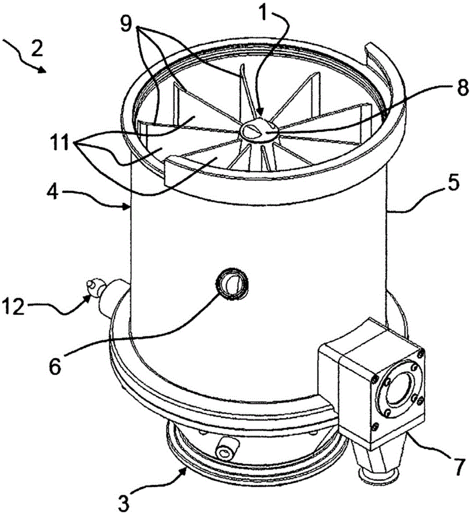
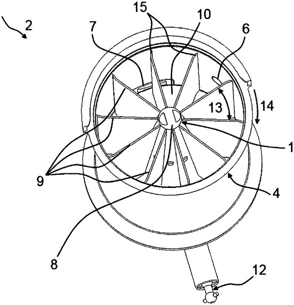
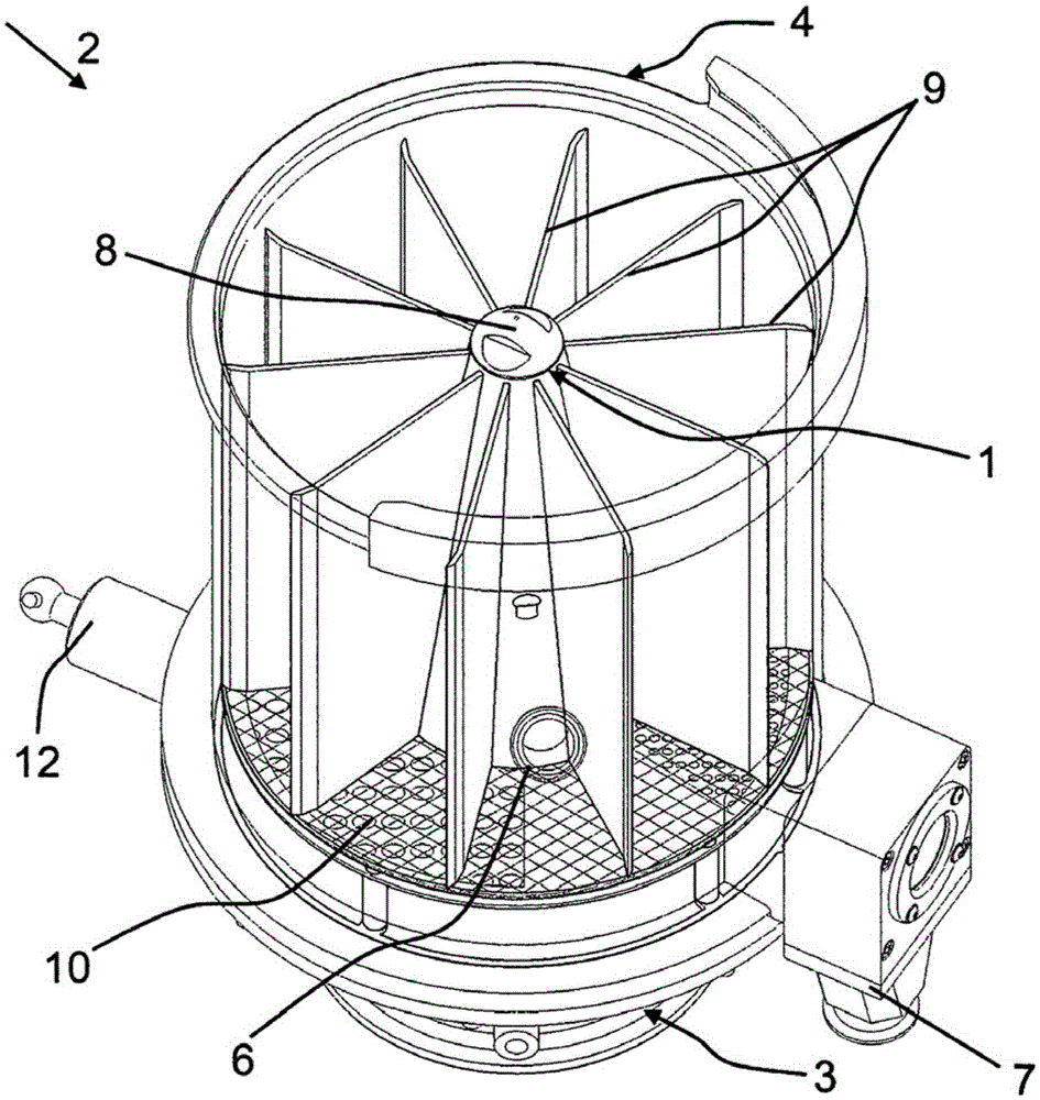
[0034] figure 1 shows a perspective view of an embodiment of a rotary dryer star 1 according to the invention, which is installed in a fluidization device 2 . The vortex chamber 4 arranged above the distributor chamber 3 comprises a housing 5 with a solid particle inlet unit 6 and a solid particle outlet unit 7 and a rotary dryer star 1 according to the invention rotating in the vortex chamber 4 , The star structure of the rotary dryer has a cone 8 and a partition wall 9 arranged on the cone, which is made of sheet metal, aluminum or the like, for example, and which divides the swirl chamber 4 into a plurality of subregions. The partition wall 9 extends over the entire structural height of the eddy chamber 4 . The partition wall 9 of the spin dryer star 1 , the housing 5 , the not shown inflow bottom 10 , eg a grid, and the not shown cover of the swirl chamber 4 enclose a treatment chamber 11 . The rotation of the rotary dryer star 1 according to the invention is generated b...


PUM


Abstract

The invention relates to a rotary dryer star (1) for segmenting a vortex chamber (4) into process compartments (11), said rotary dryer star (1) being rotatably arranged and having separating walls (9) or the like to convey solid particles along a conveying path, a flow receiving base (10) being detachably arranged below the rotary dryer star (1). The invention further relates to a method for spraying solid particles for the purpose of agglomeration, coating, layering, spray granulation or pelletization, the spectrum of residence time of the solid particles in the fluidization apparatus (2) being at least in the range of 1:3 (or alternativelytRTD90 less than or equal to 3 tRTD10).

Description

technical field [0001] The invention relates to a rotary dryer star arrangement of the type according to claim 1 for subdividing a vortex chamber into a plurality of treatment chambers and a method of the type according to claim 9 for the treatment of solid particles. Background technique [0002] Fluidization plants of the prior art have long processed solid particles using a star arrangement of continuously operating rotary dryers for rotation about a vertical center axis in a vortex chamber, which is thus divided into a plurality of treatment chambers. In particular, a constant and precisely defined residence time of the solid particles in the fluidization device can be achieved by means of the star arrangement of the rotary dryers in the vortex chamber rotating about a vertical center axis. [0003] Patent document DE-PS1227840B proposes a continuously working vortex bed dryer for bulk materials. This vortex bed dryer consists of a shaft-shaped drying chamber, a sieve b...

Claims


Application Information

Patent Timeline
IPC IPC(8): B01J2/16F26B7/00F26B17/10
CPCB01J2/16F26B7/007F26B17/104B01J2/006B01J2208/00557B01J8/38B01J8/44F26B11/028
Inventor M·雅各布R·波贝尔R·皮拉H·普利梓克
Owner GLATT INGENIEURTECHNIK GMBH
Learn More