
Power generator rotor vertical maintenance auxiliary support device

A generator rotor and auxiliary support technology, applied in the manufacture of stator/rotor body, etc., can solve the problems of inconvenient rotor inspection, excessive rotation, incomplete inspection, etc., and achieve the effect of shortening the number of inspections, simple structure, and convenient inspection

Inactive Publication Date: 2016-02-24
南宁市春江电控技术研究所
View PDF7 Cites 1 Cited by
  • Summary
  • Abstract
  • Description
  • Claims
  • Application Information

AI Technical Summary

Problems solved by technology

[0002] The rotor in the generator is an important part for winding the coil. When the rotor is damaged, the entire generator set cannot continue to be used. When performing rotor maintenance, most of the existing methods are to place the rotor on the ground, and then maintenance personnel The rotor needs to be rotated in a timely manner to facilitate coil winding or other maintenance work. The rotor is large in size and heavy in mass, so manual rotation can easily lead to excessive rotation or cause safety accidents. At the same time, the rotor in the prior art only It can be placed horizontally, it is not convenient to check the inside of the rotor, and it is easy to cause accidents of incomplete maintenance, and it needs to be disassembled and repaired later, which is more troublesome

Method used


Image

  • Power generator rotor vertical maintenance auxiliary support device
  • Power generator rotor vertical maintenance auxiliary support device
  • Power generator rotor vertical maintenance auxiliary support device

Examples


Embodiment Construction

[0017] The preferred embodiments of the present invention will be described in detail below in conjunction with the accompanying drawings, so that the advantages and features of the present invention can be more easily understood by those skilled in the art, so as to define the protection scope of the present invention more clearly.

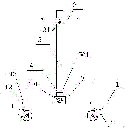
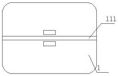
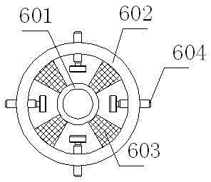
[0018] refer to figure 1 , figure 2 and image 3 The shown generator rotor vertical maintenance auxiliary support device includes a base plate 1, the base plate 1 is made of steel, the thickness of the base plate 1 is 10 mm, and four universal wheels are symmetrically arranged on the bottom of the base plate 1 2. Screws (not shown) are fitted between the universal wheel 2 and the bottom plate 1, and two clips 3 are arranged on the top of the bottom plate 1, and a clip is formed between the two clips 3. A rotating rod 4 is fitted in the bayonet, and a bolt 401 is fitted between the rotating rod 4 and the clamping plate 3. By adjusting the tight...


PUM


Abstract

The present invention discloses a power generator rotor vertical maintenance auxiliary support device which comprises a bottom plate. The bottom of the bottom plate is symmetrically provided with four universal wheels. The top of the bottom plate is provided with two clamp plates, a bayonet is formed between the two clamp plates, and a rotation rod is matched in the bayonet. Bolts are matched between the rotation rod and the clamping plates. The top of the rotation rod is provided with an embedded hole. A roller bearing is matched in the embedded hole. A circumferential direction rotation rod is matched above the rotation rod. The lower end of the circumferential direction rotation rod is matched with an insertion rod which is matched in the roller bearing. A rotor axis positioning device is matched on the circumferential direction rotation rod. According to the device, the rotor of a power generator can be positioned well, the circumferential direction rotation of the power generator rotor can be realized at the same time, the maintenance is convenient, the power generator rotor can be vertically placed to conveniently inspect the internal part, the missed maintenance is avoided, and the times of maintenance are shortened.

Description

technical field [0001] The invention relates to an auxiliary supporting device for vertical maintenance of a generator rotor. Background technique [0002] The rotor in the generator is an important part for winding the coil. When the rotor is damaged, the entire generator set cannot continue to be used. When performing rotor maintenance, most of the existing methods are to place the rotor on the ground, and then maintenance personnel The rotor needs to be rotated in a timely manner to facilitate coil winding or other maintenance work. The rotor is large in size and heavy in mass, so manual rotation can easily lead to excessive rotation or cause safety accidents. At the same time, the rotor in the prior art only It can be placed horizontally, and it is not convenient to check the inside of the rotor, which is likely to cause accidents of incomplete maintenance, and it needs to be disassembled and repaired later, which is troublesome. [0003] Based on the above problems, it...

Claims


Application Information

Patent Timeline
Patent Type & Authority Applications(China)
IPC IPC(8): H02K15/02
Inventor 卢嘉兴
Owner 南宁市春江电控技术研究所
Learn More