
A gas drilling bottom near the drill bit continuous shock source nipple

A gas drilling and near-bit technology, which is applied to natural gas drilling equipment and oil fields, can solve the problems of low excitation energy, affect drilling safety, and large attenuation of reflected wave information, and achieve stable excitation energy, simple operation mode, and wide signal frequency bandwidth. Effect

Active Publication Date: 2017-07-04
SOUTHWEST PETROLEUM UNIV
View PDF7 Cites 0 Cited by
  • Summary
  • Abstract
  • Description
  • Claims
  • Application Information

AI Technical Summary

Problems solved by technology

This method has the following problems during use: (1) It is only suitable for roller cone bits and cannot be used for PDC bits; (2) The vibration of the drill bit is random and the impact energy is small; (3) The rotation of the bottom hole drill bit It will affect the reception of the bottom hole reflection wave. At the same time, the vibration of the bottom hole assembly will also affect the vibration of the drill bit; (4) The vibration of the downhole drill bit is not suitable for soft formations, deep well sections and horizontal well sections. The reflected wave information collected by the surface in the extended-reach well has a large attenuation
Among them, the electric spark source and the air gun source are suitable for offshore operations, not suitable for gas drilling; the pneumatic source is to introduce combustible gas into the explosion chamber, and then detonate it by electric sparks. The pulse generated during the explosion is transmitted from the bottom plate of the explosion chamber to the ground , the large reaction force of the seismic source requires high drilling pressure and high requirements for the strength of the explosion chamber, which affects drilling safety, and the excitation energy of a single impact is low, requiring multiple excitations; the heavy hammer seismic source requires a large weight of the hammer, which is not easy It is used for downhole operations, and the energy of a single impact is limited and the consistency is poor
[0005] In addition, the air hammer used in the gas drilling process generates a pulse shock source through the continuous impact of the piston on the hammer head, and the frequency-sweeping hydraulic pulse jar quickly cuts off the mud flow in the flow channel through a self-driven diverter valve to generate a pulse shock. Although the air hammer and Both swept frequency hydraulic pulse jars can be used as downhole sources, but both types of sources also encounter difficulties in application
First of all, in order to obtain the random distribution of the impact rate, hundreds or even thousands of impacts are required, and the receiving time can usually reach several minutes. Conventional seismic recording instruments cannot meet the requirements, and special seismic recording instruments are needed to achieve it. The long impact time also reduces the efficiency of exploration and construction, increases the construction cost, and affects the operation time and safety of drilling
Secondly, despite the large number of impacts, it is difficult to obtain a truly random sequence due to the inherent limitations of the air hammer and the frequency-sweeping hydraulic pulse jar, so severe correlation noise will have a great impact on the signal-to-noise ratio of seismic records

Method used


Image

  • A gas drilling bottom near the drill bit continuous shock source nipple
  • A gas drilling bottom near the drill bit continuous shock source nipple
  • A gas drilling bottom near the drill bit continuous shock source nipple

Examples


Embodiment Construction

[0035] The present invention will be further described below in conjunction with the accompanying drawings, but the protection scope of the present invention is not limited to the following description.

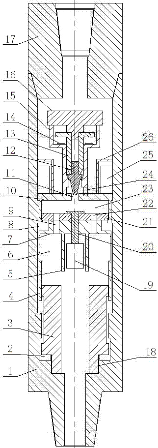
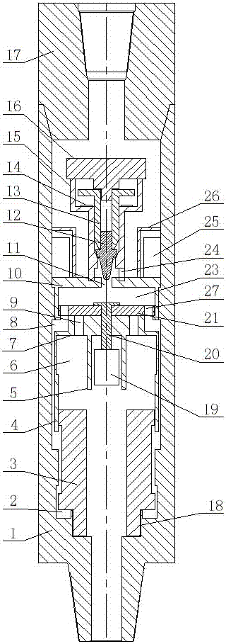
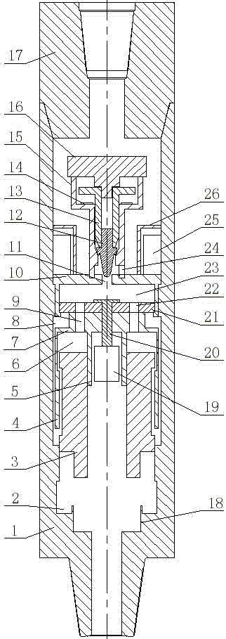
[0036] Such as figure 1 , figure 2 and image 3 As shown, a gas drilling bottom near the drill bit continuous shock source nipple, which includes a shorting body, a cylinder block, a piston 3 and a gas distribution device. The shorting body is formed by connecting the shell 1 and the upper joint 17. The connection method is taper thread, which has good sealing performance and can effectively prevent gas leakage.

[0037] The cylinder block is installed in the shell 1, the cylinder block includes the outer wall of the cylinder 4, the inner wall of the cylinder 5 and the bottom 7 of the cylinder block, the piston 3 is installed between the outer wall 4 of the cylinder and the inner wall 5 of the cylinder, and the piston 3 Can reciprocate in the cylinder body.

[0038] A lo...


PUM


Abstract

The invention relates to a gas drilling shaft bottom near-bit continuous impact focus nipple, comprising a nipple body, a cylinder body, a piston (3) and a gas distribution device, wherein the cylinder body is arranged in a shell (1), the piston (3) is arranged in the cylinder body, a lower gas inlet passage (8) is formed between the cylinder body and the shell (1), a lower gas chamber (2) is formed between the lower end of the piston (3) and the inner wall of the shell (1), the lower gas inlet passage (8) is communicated with the lower gas chamber (2), an upper gas inlet passage (9) is formed at the bottom (7) of the cylinder body, an upper gas chamber (6) is formed between the upper end of the piston (3) and the cylinder body, the upper gas inlet passage (9) is communicated with the upper gas chamber (6), and the gas distribution device is arranged at the upper part of the cylinder body. According to the focus nipple, a focus in seismic exploration is applied to a shaft bottom near a bit, a focus linear (Chirp) scanning technology can be combined with a Mini-SOSIE technology, and the focus excites the ground to generate linear scanning pulse signals through a pulse coding technology, so that the excitation quality of seismic wave is improved.

Description

technical field [0001] The present invention relates to the technical field of oil and natural gas drilling equipment, in particular to a continuous shock source nipple near the drill bit at the bottom of a gas drilling well. It can be used for formation information while drilling and prediction of drill bit position. Background technique [0002] In recent years, in the process of drilling horizontal wells and highly deviated wells with gas, the phenomenon that the drill bit deviates from the drilling trajectory often occurs. The reason for this phenomenon is usually the design error in the design process of the wellbore trajectory. In order to solve the above problems, during drilling, the seismic waves generated by the vibration near the drill bit at the bottom of the hole can be used to locate the drill bit trajectory and modify the wellbore trajectory in time. For example, when drilling a vertical well section, the vibration near the bottom of the well is received by p...

Claims


Application Information

Patent Timeline
Patent Type & Authority Patents(China)
IPC IPC(8): G01V1/137
CPCG01V1/137
Inventor 李皋简旭陈一健张蕴榕孟英峰夏文鹤简瑞
Owner SOUTHWEST PETROLEUM UNIV
Learn More