Segmentation type multi-stage centrifugal pump

A centrifugal pump, segmental technology, applied in the field of segmental multi-stage centrifugal pumps, can solve problems such as cracking, reduced life of sliding bearings, increase in vibration and noise of segmental multi-stage centrifugal pumps, etc., to improve performance and life , improve efficiency, and ensure safe and reliable operation

Inactive Publication Date: 2016-02-24
池泉
View PDF0 Cites 3 Cited by
  • Summary
  • Abstract
  • Description
  • Claims
  • Application Information

AI Technical Summary

Problems solved by technology

However, during the working process of the segmental multistage centrifugal pump, when the shaft sleeve passes through the straight groove on the sliding bearing, there is not enough lubricating film to provide sufficient carrying capacity, and the lubricating film near the sliding bearing groove ruptures, resulting in solid and solid The direct contact of the pump shaft sleeve and the sliding bearing groove produces a collision. The frequency of the collision between the pump shaft sleeve and the sliding bearing groove is the product of the rotation frequency of the pump shaft sleeve and the number of grooves on the inner wall of the sliding bearing. Therefore, the pump shaft sleeve and the sliding bearing groove Continuous collision will bring some negative problems: one is that the vibration and noise of the segmental multistage centrifugal pump increase, and the other is that the life of the sliding bearing supported by its suction end is reduced

Method used


Image

  • Segmentation type multi-stage centrifugal pump
  • Segmentation type multi-stage centrifugal pump
  • Segmentation type multi-stage centrifugal pump

Examples


Embodiment Construction

[0048] The following will clearly and completely describe the technical solutions in the embodiments of the present invention with reference to the drawings in the embodiments of the present invention.

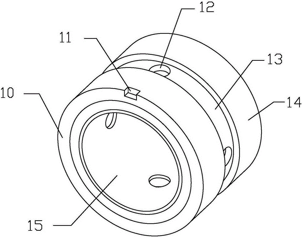
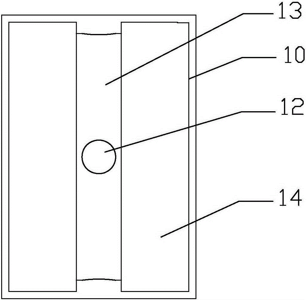
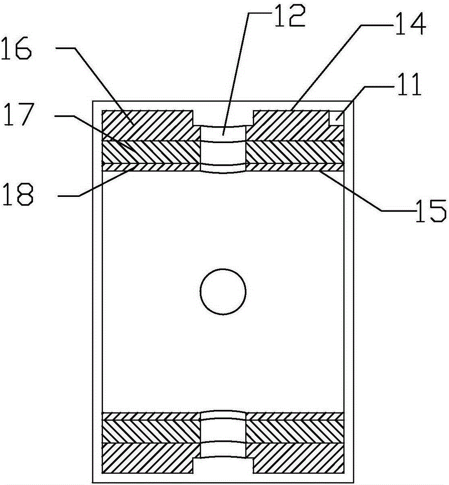
[0049] figure 1It is a schematic diagram of the segmental multistage centrifugal pump of the present invention. As shown in the figure, the segmental multistage centrifugal pump of the present invention specifically includes: a base 1, a bearing seat 2, a shaft sleeve 3, a sliding bearing 4, a suction section 5, Retaining ring 6, pump shaft 7, impeller spacer ring 8, primary impeller 9, impeller guide vane 10, middle section 11, secondary impeller 12, discharge section 13, mechanical seal 16, rolling bearing 17, coupling 18, motor bracket 19 And the motor 20, wherein the discharge section 13 is connected to the motor bracket 19 through bolts 15 and nuts 14, and the mechanical seal 16 is used to seal between the discharge section 13 and the pump shaft 7.

[0050] The segmental...


PUM


Abstract

The invention discloses a segmentation type multi-stage centrifugal pump. The segmentation type multi-stage centrifugal pump comprises a sucking section, a first-stage impeller, impeller guide blades, a middle section, a second-stage impeller, a discharging section, a pump shaft, a shaft sleeve, an impeller spacer ring, a sliding bearing connected to the outer side of the shaft sleeve in a sleeving mode, a rolling bearing, an elastic connector connected with the pump shaft and an external prime mover driving the pump shaft to rate through the elastic connector. A plurality of spiral grooves are formed in the inner wall of the sliding bearing; the impellers are assembled on the pump shaft in a key-connection mode; the impeller guide blades are assembled in the middle section. Liquid is pressurized through the impellers and collected through the impeller guide blades, the flow speed is lowered, and the liquid is discharged through the discharging section and fed into a pipeline system. The spiral grooves in the inner wall of the sliding bearing increase the circulation amount of fluid and guarantee good lubrication of the sliding bearing, and therefore the friction power consumption between the shaft sleeve and the sliding bearing is lowered, and the mechanical efficiency of the centrifugal pump is improved. The heat caused by friction between the sliding bearing and the shaft sleeve is taken away in time, the service life of the sliding bearing is prolonged, and safe and reliable operation of the centrifugal pump is guaranteed.

Description

technical field [0001] The invention relates to the fields of liquid transportation such as industry and agriculture, in particular to a sliding bearing and a vertically installed segmented multistage centrifugal pump. Background technique [0002] Segmental multistage centrifugal pump is to install multiple impellers on a shaft to work in series, and the number of impellers on the shaft represents the number of stages of the pump. The segmental multistage pump structure is generally divided into a suction section, a middle section (the number of the middle section is the number of impellers minus 1) and a discharge section, and each section is connected as a whole with tension bolts. The suction ports of the segmental multi-stage centrifugal pump are arranged in the same direction. The liquid flows out from the previous stage impeller and enters the inlet of the next stage impeller through the guide vane, so that the energy increases step by step, and finally flows out th...

Claims


Application Information

Patent Timeline
Patent Type & Authority Applications(China)
IPC IPC(8): F04D1/06F04D13/06F04D29/046F04D29/049F04D29/42F04D29/44F04D29/22F04D29/20F04D29/66
CPCF04D1/06F04D1/063F04D13/06F04D29/046F04D29/0462F04D29/049F04D29/06F04D29/185F04D29/20F04D29/2222F04D29/426F04D29/448F04D29/669F05D2240/12
Inventor 陈拥军
Owner 池泉
Why Eureka
Try Eureka