Runner cycloid speed changing stress application mechanism

A technology of booster mechanism and runner, which is applied in the field of crankshaft transmission machinery and variable speed transmission machinery, and can solve the problems of high power consumption under gas pressure, low vibration and energy efficiency, and insufficient combustion.

Pending Publication Date: 2016-02-24
南通金鼎天轮动力科技有限公司
View PDF0 Cites 1 Cited by
  • Summary
  • Abstract
  • Description
  • Claims
  • Application Information

AI Technical Summary

Problems solved by technology

[0002] There are many kinds of transmission mechanisms of the current piston reciprocating fluid power machinery, but there are many defects; taking the compressor of the crank-link mechanism as an example, the crankshaft pushes the piston to reciprocate through eccentric rotation, and the piston compresses the gas. The gas pressure of the gas is constantly rising, and the back pressure on the piston is constantly increasing, and the crankshaft must overcome the rising reaction force under the condition of constant power input, and there must be many defects such as vibration and low energy efficiency; the piston internal combustion compressor is used as the main For example, the crankshaft pushes the piston to carry out the compression stroke, and the piston is exposed to the increasing gas pressure, which consumes a lot of power; the piston stays near the top dead center during the expansion stroke for a relatively short time, and the energy efficiency is low due to insufficient combustion

Method used


Image

  • Runner cycloid speed changing stress application mechanism
  • Runner cycloid speed changing stress application mechanism
  • Runner cycloid speed changing stress application mechanism

Examples


Embodiment Construction

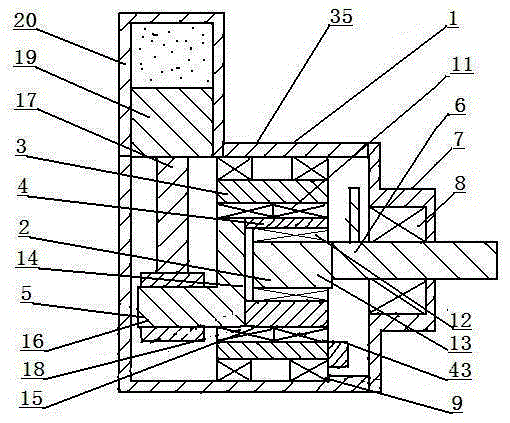
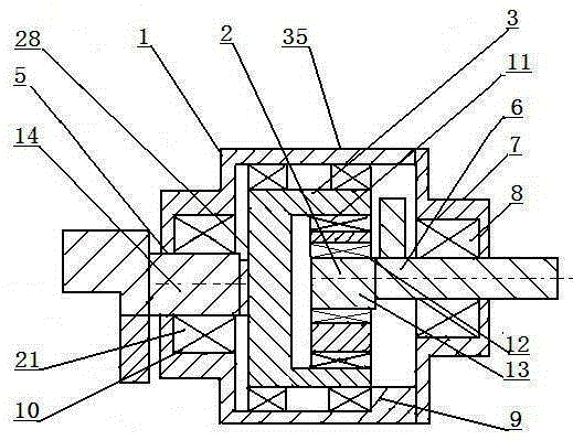
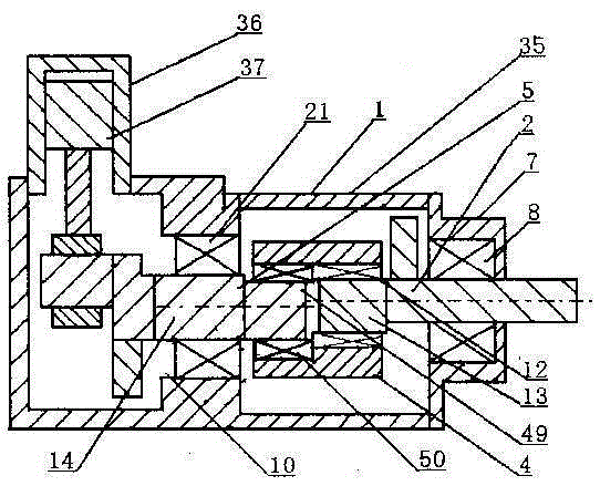
[0028] Such as figure 1 , Figure 5 , Figure 6 As shown, a runner cycloidal speed change boosting mechanism 35 is made up of body 1, crankshaft 2, runner 3, cycloid wheel 4 and crankshaft 5; crankshaft 2 is an input shaft, crankshaft 5 is an output shaft, and the runner 3 and cycloid wheel 4 are cycloid control devices. The shaft body 6 of the crankshaft 2 is supported and installed in the bearing seat 8 of the frame 7 of the body 1, the bearing support of the runner 3 is installed in the bearing seat 9 inside the body 1, and the runner 3 is installed eccentrically relative to the shaft body 6 of the crankshaft 2 , Balance weight 43 is installed on the running wheel 3. There is an eccentric bearing raceway 11 on the runner 3, the shaft body 15 of the cycloidal wheel 4, and the bearing support is installed in the eccentric bearing raceway 11 of the runner 3, and the inside of the cycloidal wheel 4 is provided with an eccentric bearing raceway 12, The journal 13 of the cranks...


PUM


Abstract

A runner cycloid speed changing stress application mechanism is composed of a machine body (1), a bent axle (2), a runner (3), a cycloidal wheel (4) and a bent wheel axle (5). The runner (3) is eccentrically installed relative to an axle body (6) of the bent axle (2). A wheel body (15) of the cycloidal wheel (4) is installed in an eccentric bearing roller path (11) of the runner (3) in a bearing support manner. An axle neck (13) of the bent axle (2) is installed in an eccentric bent axle roller bath (12) of the cycloidal wheel (4) in a bearing support manner. The bent axle (2) rotates by a circle at a constant speed, and the bent wheel axle (5) rotates by a circle in a speed changing manner under the effect of revolution and rotation of the cycloidal wheel (4). When the bent axle (2) is in the constant power input condition, according to the fact that the power is equal to the product of force and speed, when the bent wheel axle (5) decelerates, the torsion is increased, and accordingly the constantly-increasing reverse acting force, generated in the compression exhaust stroke, of a piston (19) is overcome.

Description

technical field [0001] The invention relates to a rotary cycloid variable speed booster mechanism for piston reciprocating fluid power mechanical transmission, which relates to the technical field of fluid power machinery manufacturing such as pumps, compressors and engines, and is used for crankshaft transmission machinery and variable speed transmission machinery technology field. Background technique [0002] There are many kinds of transmission mechanisms of the current piston reciprocating fluid power machinery, but there are many defects; taking the compressor of the crank-link mechanism as an example, the crankshaft pushes the piston to reciprocate through eccentric rotation, and the piston compresses the gas. The gas pressure of the gas is constantly rising, and the back pressure on the piston is constantly increasing, and the crankshaft must overcome the rising reaction force under the condition of constant power input, and there must be many defects such as vibrati...

Claims


Application Information

Patent Timeline
IPC IPC(8): F01B9/02F02B75/32F04C21/00
Inventor 周觉明
Owner 南通金鼎天轮动力科技有限公司
Why Eureka
Try Eureka