Prefabricated construction method for prestressed concrete box girder
A concrete box girder and construction method technology, applied in the direction of manufacturing tools, ceramic molding machines, molds, etc., can solve problems such as unbalanced grouting stress, low pass rate of steel bar protective layer, and inaccurate steel bar processing size, etc., to achieve improvement Thickness of box girder reinforcement cover, good post-construction effect, good economic and social benefits
Active Publication Date: 2016-02-24
安徽水利开发有限公司
View PDF6 Cites 41 Cited by
- Summary
- Abstract
- Description
- Claims
- Application Information
AI Technical Summary
Problems solved by technology
The existing prefabricated construction method of prestressed box girder is still immature, so there are many defects in prestressed box girder, mainly: inaccurate steel bar processing size, uneven installation spacing, irregular line shape, and low qualified rate of steel bar protection layer ; Manua
Method used
View moreImage
Smart ImageViewing Examples
Examples
 PUM
| Property | Measurement | Unit |
|---|---|---|
| Length | aaaaa | aaaaa |
| Thickness | aaaaa | aaaaa |
Abstract
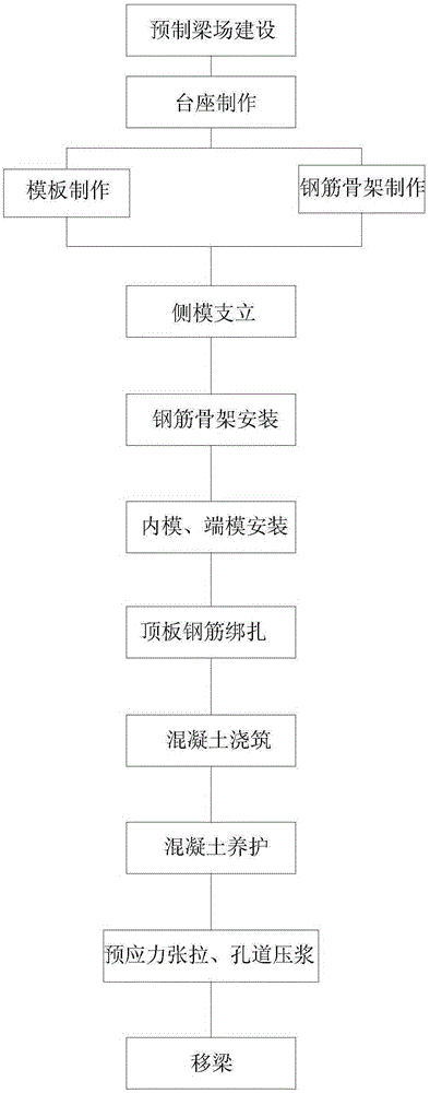
Provided is a prefabricated construction method for a prestressed concrete box girder. Firstly, a prefabricated girder field is constructed; a prefabricated pedestal is manufactured in a prefabricated area; a lateral mold is erected on the pedestal; a steel reinforcement framework is put into the lateral mold; an inner mold and an end mold are installed; then concrete pouring and concrete maintenance are conducted; after the intensity of the concrete reaches 90% of the designed intensity and the maintenance time is longer than 7 days, prestress tension and grouting of a pore canal are conducted; and after the intensity of a grouting test block in the box girder pore canal reaches 90% of the designed value, the grouting test block is moved to a girder storage area. Steel reinforcement machining is conducted through a numerical control steel reinforcement bending machine, so that the machining precision and efficacy of steel reinforcement are improved; an automatic spraying and maintaining system is adopted, so that accuracy of maintenance time and reliability of maintenance quality are ensured; an intelligent tensioning and grouting system is adopted, so that automation and refinement of tensioning and grouting are achieved; a sliding contact line power supply system is adopted, so that power use safety is ensured. The standardization, factorization, intelligence, refinement and automation of the prefabricated construction method for the prestressed concrete box girder are achieved.
Description
technical field [0001] The invention relates to the field of bridge construction, in particular to a prefabricated construction method of a prestressed concrete box girder applied to bridge construction. technical background [0002] Concrete box girders are used in bridge construction. The commonly used concrete box girder structures are cast-in-place prestressed concrete box girders and prefabricated prestressed box girders. The cast-in-place construction method is generally the pouring construction of the full house support on site, and it is difficult to erect the full house support on the busy road section, which seriously affects the traffic. Steel box girders are usually hoisted, and the construction is relatively simple and fast, but the project cost is high. The existing prefabricated construction method of prestressed box girder is still immature, so there are many defects in prestressed box girder, mainly: inaccurate steel bar processing size, uneven installatio...
Claims
Login to View More Application Information
Patent Timeline
 IPC IPC(8): B28B23/04B28B7/00B28B1/093B28B11/24
CPCB28B1/0935B28B7/0029B28B11/245B28B23/04
Inventor 牛曙东王礼兵杨阳李飞朱友良张海军李德明刘瑞王超费毓
Owner 安徽水利开发有限公司
Features
- R&D
- Intellectual Property
- Life Sciences
- Materials
- Tech Scout
- Unparalleled Data Quality
- Higher Quality Content
- 60% Fewer Hallucinations
Learn More Browse by: Latest US Patents, China's latest patents, Technical Efficacy Thesaurus, Application Domain, Technology Topic, Popular Technical Reports.
© 2025 PatSnap. All rights reserved.Legal|Privacy policy|Modern Slavery Act Transparency Statement|Sitemap|About US| Contact US: help@patsnap.com


