Rotor for a turbocharger device, turbocharger device having a rotor, and shaft for a rotor of said type

A technology for turbochargers and rotors, applied in parts of pumping devices for elastic fluids, machines/engines, supporting elements of blades, etc., to achieve increased reliability, improved vibration performance, and increased rotor stiffness

Active Publication Date: 2016-02-17
VTESCO TECH GMBH
View PDF6 Cites 4 Cited by
  • Summary
  • Abstract
  • Description
  • Claims
  • Application Information

AI Technical Summary

Problems solved by technology

Against this background, there are additional problems with the oil-lubricated design of bearings, which are usually designed as plain bearings, sometimes with floating bearing bushes

Method used


Image

  • Rotor for a turbocharger device, turbocharger device having a rotor, and shaft for a rotor of said type
  • Rotor for a turbocharger device, turbocharger device having a rotor, and shaft for a rotor of said type
  • Rotor for a turbocharger device, turbocharger device having a rotor, and shaft for a rotor of said type

Examples


Embodiment Construction

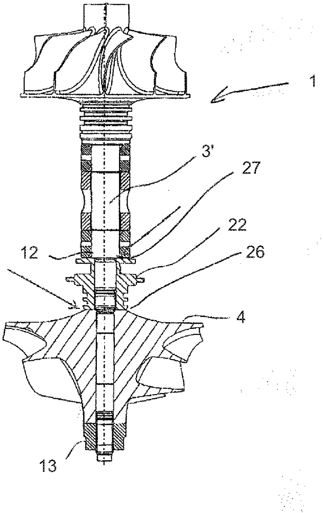
[0046] figure 1 A part of a turbocharger arrangement 2 according to the prior art is shown in a longitudinal section through the shaft of the rotor and a partial view of a housing part. On the exhaust side, the rotor has a turbine wheel 18 which is driven by the exhaust gas flow of the piston internal combustion engine. The turbine wheel 18 is mounted on a common shaft 3 with an impeller / compressor wheel 4 which delivers air in the intake passage to the intake valves of the internal combustion engine and in the piston chambers for the purpose of more efficient combustion. medium compressed air.

[0047] The compressor wheel 4 is fastened to the shaft 3 by means of a threaded nut 13 which is screwed as a central threaded connection element on the end-side external thread of the shaft 3 and presses the compressor wheel 4 with an intermediate layer of various additional elements. against the shaft shoulder.

[0048] In addition, two radial bearings 19, 20 are provided in the i...


PUM


Abstract

The invention relates to a rotor (1) for a turbocharger device (2), having a shaft (3, 3'3'') and having arranged and fixed axially one behind the other on the shaft (3, 3', 3'') an impeller wheel (4), a sealing bushing element (5) and an axial bearing element (8, 8') which rotates with the shaft, wherein the sealing bushing element (5) and the axial bearing element (8, 8'), by way of an internal thread (10, 10', 10'') provided on at least one of said elements, are screwed to a first external thread (11, 11') arranged on the shaft (3, 3', 3'') and are braced against a shaft shoulder (12). Stronger and more rigid fixing of the parts that are pushed onto the shaft, and thus also lower susceptibility to vibration-induced faults during operation, are achieved by means of this construction.

Description

technical field [0001] The invention belongs to the field of mechanics, in particular mechanical engineering, and can be applied particularly advantageously to turbocharger arrangements. Background technique [0002] Turbocharger arrangements are used on internal combustion engines in the form of piston engines for assisting the air intake of the pistons by the positive pressure provided by the incoming air. For this purpose, turbochargers usually have a turbine, which is driven by hot air in the exhaust gas flow and is fixedly mounted on the same shaft as the compressor wheel, which in turn directs the inflowing The pressure of the air increases. Considerable torque needs to be transmitted at very high speeds (tens to hundreds of thousands of rpm) through the shaft connecting the turbine to the compressor wheel. The challenges encountered during the mechanical design include, inter alia, the stability against the high temperatures prevailing in the exhaust gas flow and th...

Claims


Application Information

Patent Timeline
Patent Type & Authority Applications(China)
IPC IPC(8): F01D5/02F04D29/26
CPCF04D29/266F01D5/025F04D29/053F04D29/056F04D29/284F05D2220/40
Inventor R.贝宁R-M.肯佩尔
Owner VTESCO TECH GMBH
Why Eureka
Try Eureka