
Integrated intelligent motor protector without external power source

A technology for external power supply and motor, which is applied in the direction of motor generator/starter, starter of single multi-phase induction motor, emergency protection circuit device, etc. It can solve problems such as wiring defects, safety accidents, complicated wiring, etc., and achieve safety Improvement, prevention of false connection, high safety effect

Inactive Publication Date: 2016-02-17
山东垦创自控技术有限公司
View PDF5 Cites 0 Cited by
  • Summary
  • Abstract
  • Description
  • Claims
  • Application Information

AI Technical Summary

Problems solved by technology

The set current adopts digital setting and is operated through the buttons on the control panel. Users can modify and set various parameters on site according to the specific conditions of the motor. It is more convenient to use and has a high degree of intelligence. However, the existing intelligent motor protectors generally It adopts a split design and has a large volume, so it cannot be installed uniformly with other electrical components in the control box according to the standard installation method (such as DIN rail installation). Large, the scope of application is limited
[0007] (2) The motor protectors currently on the market are all active types, that is, they generally need to be connected to an external 220V AC power supply when working. Wiring is extremely flawed when wiring on site;
[0008] Although the power supply can also take power from the main power supply circuit of the motor, if it takes power from the downstream of the contactor, the wiring is convenient. However, in the installation stage, in order to ensure that the safety contactor is in a disconnected state, so There is no power supply downstream of the contactor to power the motor protector, and the motor protector cannot be debugged and parameterized; if the power supply of the motor protector is powered from the upstream of the contactor, although it can be Normal power supply, and the debugging of the motor protector can be successfully completed, but this wiring method is more complicated, especially does not conform to the normal wiring habits of electricians, so to a certain extent, it limits the development and promotion of the motor protector
[0009] (3) For the current motor protectors on the market, in order to collect the parameters of the motor during operation, a mutual inductance device (such as a current transformer) needs to be connected in series in the power supply circuit of the motor, and the wiring is more complicated
[0011] In the prior art, when a solid-state contactor is used as a switching device to cooperate with a motor protector, in addition to the above-mentioned various defects, there are also the following defects: because the thyristor generally used in a solid-state contactor As a switching element connected in series in the main circuit, in order to prevent the reverse power supply in the circuit from breaking down the thyristor in the solid-state contactor, a resistance-capacitance protection circuit is generally installed at the output end of the main contact of the solid-state contactor
[0012] In the on-site debugging stage, no-load debugging is generally carried out, that is, when the end of the main circuit is not connected to any load (such as a motor). The control circuit inside the RC protection circuit continuously charges the capacitor in the RC protection circuit. Since there is no load connected to the end of the solid-state contactor, the power supply in the RC protection circuit cannot be released to generate leakage current, so the leakage current is very easy to The commissioning personnel were injured by electricity, causing safety accidents and not conducive to the smooth progress of commissioning

Method used


Image

  • Integrated intelligent motor protector without external power source
  • Integrated intelligent motor protector without external power source
  • Integrated intelligent motor protector without external power source

Examples


Embodiment 2

[0083] The difference between Embodiment 2 and Embodiment 1 is that in this embodiment, the contactor in the motor power supply circuit adopts a common electromagnetic contactor. Since the electromagnetic contactor is used, when the motor power supply circuit is empty, there is no leakage current at the end of the main contact of the electromagnetic contactor, so if Figure 9 As shown, in this embodiment, the current elimination unit in Embodiment 1 is omitted.

Embodiment 3

[0085] The difference between Embodiment 3 and Embodiment 1 is that in the current canceling unit of this embodiment, three bleeder resistors are provided and a single normally closed contact of a relay is used. Such as Figure 7 Shown: One end of resistors R4~R6 are respectively connected in parallel with phase line A, phase line B and phase line C, and the other ends of resistors R4~R6 are respectively connected in series with normally closed contacts K2-1~K2-3. Resistors R4~R6 are discharge resistors, and normally closed contacts K2-1~K2-3 are respectively normally closed contacts of relay K2 (not shown in the figure). When debugging, when the end of the three-phase line of AC A, B, and C is not connected to a load (such as a motor), since there is no current in the three-phase line of AC A, B, and C at this time, the microprocessor does not send a signal to the relay. K2 sends the drive signal, so a loop is formed between the AC three-phase lines A, B, C and the discharge...

Embodiment 4

[0087] The difference between Embodiment 4 and Embodiment 1 is that in this embodiment, the magnetic latching relay in the self-holding electronic switch is replaced by a manual reset relay. After the microprocessor in the control setting unit drives the manual reset relay to act, the normally closed contact inside it is disconnected, and the motor starting circuit is disconnected. The normally closed contacts in the manual reset relay will not automatically reset after the action. After the on-site failure is confirmed to be removed, the on-site staff manually presses the reset button on the manual reset relay, and now the normally closed contact in the manual reset relay returns to the closed state again, which has played the same technical effect as in embodiment 1. The reset is realized manually by the staff, and the safety is greatly improved.


PUM


Abstract

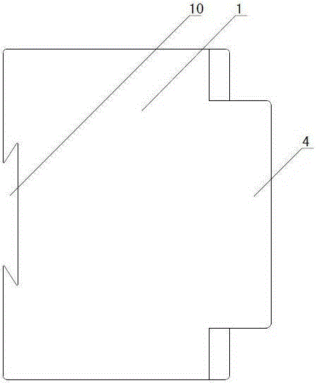
The invention discloses an integrated intelligent motor protector without an external power source and belongs to the technical field of motor protection. The motor protector comprises a shell and a control circuit fixed in the shell. The motor protector is characterized in that the shell comprises an outer shell body (1) and a control panel (4) arranged on the front end face of the outer shell body (1). The outer shell body (1) is provided with a power source wire connection terminal used for being connected into a motor power supply loop in series, and a series-connection point is located at the wire outlet end of a main contact in the motor power supply loop. The control panel (4) is provided with a control wire connection terminal used for being connected into a motor starting loop in series, the control wire connection terminal is used for achieving connection and disconnection of the motor starting loop, and a power source wire connection unit and a control wire connection unit are connected to the control circuit at the same time. The integrated intelligent motor protector without the external power source is connected to the wire outlet end of the main contact of the motor power supply circuit in series, connection more conforms to the on-site wire connection habit, and no extra external power source is needed.

Description

technical field [0001] An integrated intelligent motor protector without external power supply belongs to the technical field of motor protection. Background technique [0002] The motor protector is an electrical device that comprehensively protects the motor during operation. In the prior art, before using the motor protector, it is first necessary to set the action parameters of the motor protector through the buttons on the motor protector. After the setting is completed, connect the motor protector to the AC main The operating parameters are monitored. When the operating parameters of the motor are abnormal or reach the preset action parameters, the motor protector will cut off the main power supply circuit of the motor to protect the motor. [0003] At present, the electromagnetic contactor is generally used as the switching device of the motor to be connected in series in the power supply circuit of the motor, and the motor protector is arranged between the contactor...

Claims


Application Information

Patent Timeline
Patent Type & Authority Applications(China)
IPC IPC(8): H02H7/08H02P1/26
Inventor 董法军商晓
Owner 山东垦创自控技术有限公司
Learn More