
Camera movement control method

A motion control and camera technology, applied in the direction of control without feedback, can solve the problem of low appearance efficiency of the chip, and achieve the effect of simple and stable control method and circular motion.

Inactive Publication Date: 2016-02-17
CHONGQING YUANCHUANG PHOTOELECTRIC TECH CO LTD
View PDF6 Cites 0 Cited by
  • Summary
  • Abstract
  • Description
  • Claims
  • Application Information

AI Technical Summary

Problems solved by technology

[0003] In view of the shortcomings of the prior art described above, the purpose of the present invention is to provide a camera motion control method for solving the problem of low efficiency in the prior art of using manual methods to detect the appearance of chips

Method used


Image

  • Camera movement control method
  • Camera movement control method

Examples


Embodiment Construction

[0021] The implementation of the present invention will be illustrated by specific specific examples below, and those skilled in the art can easily understand other advantages and effects of the present invention from the contents disclosed in this specification.

[0022] It should be noted that the structures, proportions, sizes, etc. shown in the drawings attached to this specification are only used to match the content disclosed in the specification, for those who are familiar with this technology to understand and read, and are not used to limit the implementation of the present invention. Limiting conditions, so there is no technical substantive meaning, any modification of structure, change of proportional relationship or adjustment of size, without affecting the effect and purpose of the present invention, should still fall within the scope of the present invention. The disclosed technical content must be within the scope covered. At the same time, terms such as "upper"...


PUM


Abstract

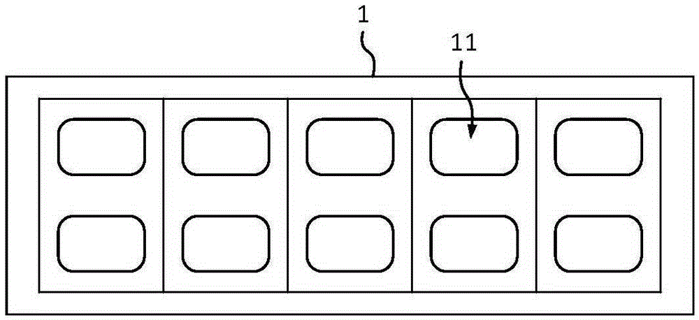
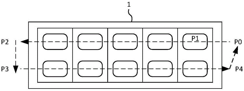
The invention provides a camera movement control method. Due to the fact that the maximum speed is set for camera movement, it is guaranteed that a camera can do uniform movement, and the accuracy of image acquisition is provided; in addition, a circulation path is formed by the first preset position, the second preset position, the third preset position and the fourth preset position, chip image acquisition can be achieved on a back-and-forth path of the camera movement, and the maximum efficiency is achieved. According to the camera movement control method, movement photographing of a chip can be completed in a 2*5 chip frame within 10 s, and the detection efficiency is four times higher than the manual detection efficiency.

Description

technical field [0001] The invention relates to the technical field of mechanical motion control, in particular to a camera motion control method. Background technique [0002] In the existing chip production process, the appearance of the chip is generally inspected manually to exclude defective products. However, this method is not efficient and highly dependent on people, requiring experienced people to operate. Therefore, those skilled in the art try to use image technology to detect the appearance of chips, but how to quickly obtain chip images to provide samples for image detection has become a difficult problem for those skilled in the art. Contents of the invention [0003] In view of the above-mentioned shortcomings of the prior art, the purpose of the present invention is to provide a camera motion control method for solving the problem of low efficiency in the prior art of using manual methods to detect the appearance of chips. [0004] In order to achieve the...

Claims


Application Information

Patent Timeline
Patent Type & Authority Applications(China)
IPC IPC(8): G05D3/10
CPCG05D3/10
Inventor 李志远耿世慧李熙春
Owner CHONGQING YUANCHUANG PHOTOELECTRIC TECH CO LTD
Learn More