Operation device of stove and stove
An operating device and cooker technology, applied in the cooker field, can solve problems such as color interference, unsuitable color, and users' inability to accurately identify firepower/power
- Summary
- Abstract
- Description
- Claims
- Application Information
AI Technical Summary
Problems solved by technology
Method used
Image

Examples
Embodiment 1
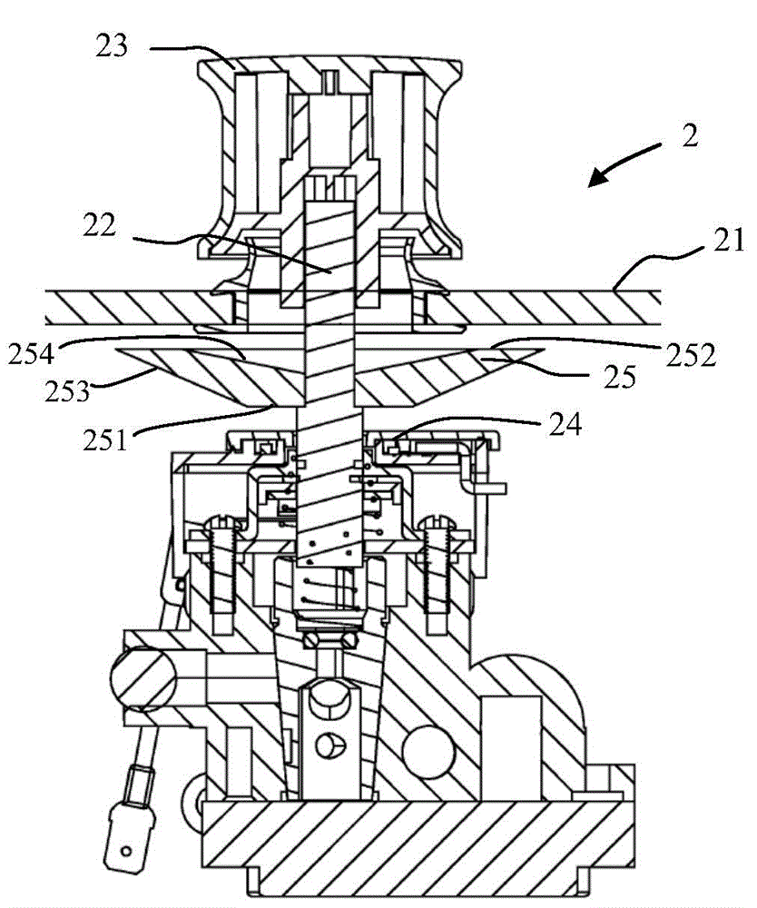
[0044] Please refer to figure 1 , figure 1 It is a cross-sectional view of the operating device of the cooktop according to Embodiment 1 of the present invention. The operating device 2 includes a panel 21 , a rotating shaft 22 , a knob 23 and a light emitting element 24 . The rotating shaft 22 is at least partially located inside the panel 21 . The operating device 2 has at least two gear positions, and the gear position of the operating device 2 can be adjusted by turning the rotating shaft 22 . The knob 23 is at least partly located outside the panel 21 and sleeved on the rotating shaft 22 for driving the rotating shaft 22 to rotate. The light emitting element 24 is located inside the panel 21 .
[0045] The operating device 2 further includes a light guide member 25 connected to the rotating shaft 22 and driven by the rotating shaft 22 to rotate when the rotating shaft 22 rotates. The light guiding member 25 is located between the light emitting member 24 and the panel...
Embodiment 2
[0050] The same or corresponding structures of this embodiment and the first embodiment have the same or corresponding reference numerals, and their functions are also the same or similar, so details will not be repeated here, please refer to the corresponding description of the first embodiment. Different from Embodiment 1, the panel 21' of this embodiment has a light-transmitting region 300 and a fourth opaque region 304 surrounding the light-transmitting region 300. That is, the panel 21' is opaque except for the light-transmitting region 300, such as Figure 9 as shown, Figure 9 It is the front view of the panel of the second embodiment of the present invention. like Figure 10 as shown, Figure 10 It is a three-dimensional view of the light-emitting element of the second embodiment of the present invention. The light emitting surface 252' of the light-emitting element 25' in this embodiment has at least two light-transmitting gear marks 400, and the gear marks 400 ar...
Embodiment 3
[0053] The same or corresponding structures of this embodiment and the first embodiment have the same or corresponding reference numerals, and their functions are also the same or similar, so details will not be repeated here, please refer to the corresponding description of the first embodiment. like Figure 12 as shown, Figure 12 It is a cross-sectional view of the operating device of the cooktop according to the third embodiment of the present invention. The difference between this embodiment and the first embodiment lies in that the operating device of this embodiment further includes a light shield 26 for preventing the light from the light emitting element 24 from scattering to the panel 21 . Please refer to Figure 13 to Figure 15 , Figure 13 It is a three-dimensional view of the shading cover of Embodiment 3 of the present invention, Figure 14 is a three-dimensional view of the light guide in Embodiment 3 of the present invention, Figure 15 It is a cross-secti...
PUM
 Abstract
Description
Claims
Application Information
 - R&D
- Intellectual Property
- Life Sciences
- Materials
- Tech Scout
- Unparalleled Data Quality
- Higher Quality Content
- 60% Fewer Hallucinations
Browse by: Latest US Patents, China's latest patents, Technical Efficacy Thesaurus, Application Domain, Technology Topic, Popular Technical Reports.
© 2025 PatSnap. All rights reserved.Legal|Privacy policy|Modern Slavery Act Transparency Statement|Sitemap|About US| Contact US: help@patsnap.com