Shaft drive foldable electric bicycle
An electric bicycle and shaft transmission technology, applied in the field of transportation, can solve the problems of loss of wheel rotation, heavy weight, inability to fold, etc., and achieve the effects of reducing the loss rate, small footprint, and improving use efficiency
- Summary
- Abstract
- Description
- Claims
- Application Information
AI Technical Summary
Problems solved by technology
Method used
Image
Examples
specific Embodiment approach 1
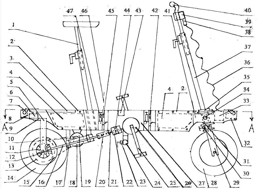
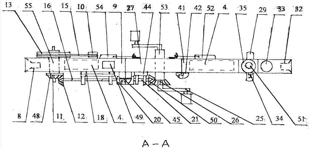
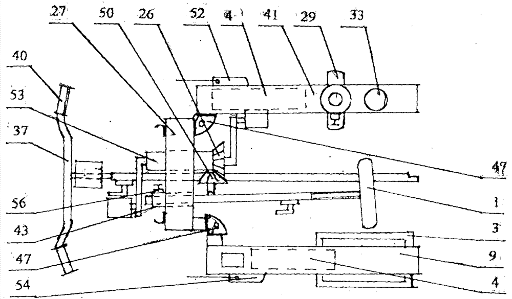
[0006] Specific implementation mode one: (see Figure 1 to Figure 6 ) The present embodiment consists of a vehicle seat assembly 1, a battery cover plate 2, a shelf 3, a battery pack 4, a rear fork 5, a rear right turn signal 6, a movable luggage rack 7, a taillight 8, a rear frame 9, a small Pulley 10, rear bevel gear a11, rear bevel gear b12, large pulley 13, rear tire 14, belt 15, rear drive shaft 16, rear bearing assembly 17, rear bearing assembly frame 18, DC motor 19, universal Section 20, front transmission shaft 21, front bearing assembly 22, handlebar placement lock device 23, handlebar placement pipe 24, big turn 25, large bevel gear 26, middle frame 27, front wheel assembly 28, front Fork assembly 29, handlebar locking device 30, fixing pipe 31, front lamp 32, spiral wire box 33, front fork locking device 34, front fork rotating assembly 35, spiral wire 36, handlebar assembly 37. Plug 38, wiring display box and socket 39, speed control handlebar cover 40, front fra...
specific Embodiment approach 2
[0007] Specific implementation mode two: (see Figure 1 to Figure 5) The difference between this embodiment and the first embodiment is that a movable shaft 58 is arranged at the front part between the bracket 57 and the handlebar placement tube 24, and an angle adjuster 59 is arranged at the rear part between the bracket 57 and the handlebar placement tube 24 , the angle regulator 59 is provided with an angle locking device 60, the bottom of the middle frame 27 is provided with a universal wheel intubation 61, and the universal wheel intubation 61 is provided with a universal wheel locking device 62, and the universal wheel 63 Insert the upper end of the universal wheel in the inserting tube 61. Place the handlebar assembly 37 horizontally, lift the movable luggage rack 7, realize the function of the luggage cart, install and fix the upper universal wheel 63, adjust the angle of the handlebar assembly 37, and realize the function of pulling the truck. Other compositions and ...
specific Embodiment approach 3
[0008] Specific embodiment three; (see Figure 1 to Figure 7 ) The difference between this embodiment and the second embodiment is that the middle part of the front hinge 42 and the rear hinge 45 is provided with a 90-degree automatic lock 47, and the 90-degree fan-shaped hole plate 68 is fixed on the front hinge 42 and the rear hinge. The left middle part of 45 and the right middle part are fixed with fan-shaped curved orifice plate 70, the shell 71 is fixed on the 90-degree fan-shaped orifice plate 68, the front end of movable pull rod 66 is provided with baffle plate 69, and the upper side of baffle plate 69 is provided with spring 67 . Other compositions and connection methods are the same as those in the second embodiment.
PUM
 Abstract
Description
Claims
Application Information
 - R&D
- Intellectual Property
- Life Sciences
- Materials
- Tech Scout
- Unparalleled Data Quality
- Higher Quality Content
- 60% Fewer Hallucinations
Browse by: Latest US Patents, China's latest patents, Technical Efficacy Thesaurus, Application Domain, Technology Topic, Popular Technical Reports.
© 2025 PatSnap. All rights reserved.Legal|Privacy policy|Modern Slavery Act Transparency Statement|Sitemap|About US| Contact US: help@patsnap.com


