Automatic ball launching device interacting with pet

An automatic launch and ball technology, applied in the field of pet toys, can solve the problems of large kinetic energy loss, low transmission power, and high power consumption, and achieve the effects of small kinetic energy loss, large transmission power, and low power consumption.

Active Publication Date: 2016-02-17
TONGFU MFG
View PDF5 Cites 4 Cited by
  • Summary
  • Abstract
  • Description
  • Claims
  • Application Information

AI Technical Summary

Problems solved by technology

Disadvantages: low transmission power, large kinetic energy loss, high power consumption, high noise, large vibration, high cost
Disadvantages: large kinetic energy loss, high power consumption, high noise, large vibration, high cost
Disadvantages: high cost, high process requirements
And not compatible with multi-size projectiles

Method used


Image

  • Automatic ball launching device interacting with pet
  • Automatic ball launching device interacting with pet
  • Automatic ball launching device interacting with pet

Examples


Embodiment 1

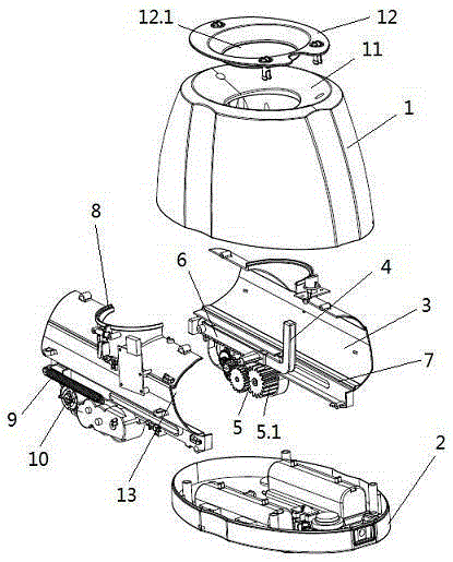
[0032] Such as Figure 1-4 The shown automatic ball launching device for pet interaction is mainly composed of an ejection channel 3, an ejection ball 14, an ejection start switch 15 and an ejection assembly;

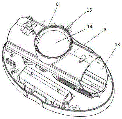
[0033] The top and the end of described ejection channel 3 are respectively provided with input port 8 and ejection hole 13 matched with ejection ball 14, and the bottom in ejection channel 3 is provided with ejection track 7; The inside is inclined downward; the ejection start switch 15 is set on the side wall of the input port 8;

[0034] The ejection assembly is mainly composed of a motor 10, a transmission gear set 5 with a tooth-missing gear 5.1, a striker 4, a rack 6 and a spring 9, and the transmission gear set 5 is connected to the motor 10 and is located at the bottom of the ejection channel 3 , the toothless gear 5.1 meshes with the rack 6, the rack 6 slides at the bottom of the ejection track 7, the rack 6 is fixedly connected to one end of the right-angle s...

Embodiment 2

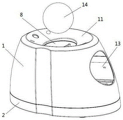
[0039] On the basis of Example 1, it also includes a shell 1 and a bottom shell 2, with special attention figure 1 and figure 2 , the ejection channel 3 and the ejection assembly are placed in the space formed by the shell 1 and the bottom shell 2, and the shell 1 is provided with holes corresponding to the input port 8, the ejection hole 13 and the ejection start switch 15 respectively. At the same time, it is also disclosed that the ejection channel 3 is composed of two half-shells separated along the center of the ejection hole.

Embodiment 3

[0041] On the basis of Example 2, pay special attention to figure 2 , the present invention also discloses that the top of the casing 1 is formed with a pitching arc 11 that is concave toward the input port 8 . Since the pitching arc 11 forms an inclined arc from top to bottom, it is convenient for the pet to put the ball into the input port 8 along the arc, reducing the difficulty of pitching.


PUM


Abstract

The invention belongs to the technical field of pet toys, and particularly provides an automatic ball launching device interacting with a pet. The automatic ball launching device is mainly composed of a catapulting channel, a catapulted ball, a catapulting starting switch and a catapulting assembly. A throwing-in opening and a catapulting hole are formed in the top and the end of the catapulting channel respectively and matched with the catapulted ball. The catapulting assembly is mainly composed of a motor, a transmission gear set with an incomplete-tooth gear, a striker, a rack and a spring. The incomplete-tooth gear is meshed with the rack, the rack is arranged at the bottom of the catapulting channel in a sliding mode and fixedly connected with one end of the right-angle striker, the other end of the striker penetrates through the catapulting channel and is limited in the catapulting channel, one end of the spring is fixed to the catapulting hole, and the other end of the spring is fixedly connected to the rack. The ball launching device is high in launching efficiency, small in kinetic energy loss, low in power consumption and compatible with launched objects of various seizes. The pet can throw the ball into the launching device by itself, automatic lunching is achieved, and the pet can play with itself when an owner can not accompany the pet.

Description

technical field [0001] The invention belongs to the technical field of pet toys, and in particular relates to an automatic ball launching device for pet interaction. Background technique [0002] With the continuous improvement of people's living standards, more and more groups keep pets, and owners can train pets through interaction with pets, and the interaction mode of throwing objects is more common. People throw balls or use specific equipment to project balls, train pet dogs to pick them up, return them to people, and repeat it many times to achieve the purpose of interacting with pets and specific training. [0003] Currently commercially available ball automatic launching apparatuses have several working principles, and their advantages and disadvantages are all very obvious. Flywheel type: It consists of a single or multiple high-speed rotating flywheels installed on the inner wall of a channel. When rotating at high speed, it squeezes the outer surface of the proj...

Claims


Application Information

Patent Timeline
Patent Type & Authority Applications(China)
IPC IPC(8): A63B69/40
CPCA63B69/407
Inventor 马耀民
Owner TONGFU MFG
Why Eureka
Try Eureka