
Charging circuit and mobile terminal

A charging circuit and circuit technology, which is applied in the electronic field, can solve the problems of high cost and high heat generation of charging circuits, and achieve the effects of improving user experience, reducing output current, and lowering production process requirements

Active Publication Date: 2016-02-10
VIVO MOBILE COMM CO LTD
View PDF5 Cites 12 Cited by
  • Summary
  • Abstract
  • Description
  • Claims
  • Application Information

AI Technical Summary

Problems solved by technology

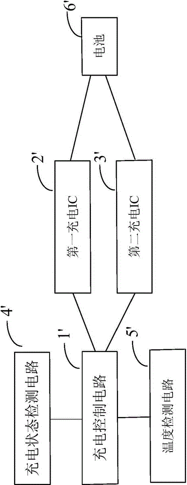
[0004] In order to overcome the problems of high cost of the charging circuit and large heat generated during charging in the prior art, an embodiment of the present invention provides a charging circuit, including a charging control circuit, and the charging circuit also includes at least two charging integrated circuits IC, so that The at least two charging ICs are connected in parallel, and their common output terminal is connected to the battery charging input terminal, and the charging control circuit is used to control the at least two charging ICs to charge the battery

Method used


Image

  • Charging circuit and mobile terminal
  • Charging circuit and mobile terminal

Examples


Embodiment Construction

[0010] In order to make the technical problems, technical solutions and beneficial effects solved by the present invention clearer, the present invention will be further described in detail below in conjunction with the accompanying drawings and embodiments. It should be understood that the specific embodiments described here are only used to explain the present invention, not to limit the present invention.

[0011] In describing the present invention, it is to be understood that the terms "longitudinal", "radial", "length", "width", "thickness", "upper", "lower", "front", "rear", The orientation or positional relationship indicated by "left", "right", "vertical", "horizontal", "top", "bottom", "inner", "outer" etc. is based on the orientation or positional relationship shown in the drawings, It is only for the convenience of describing the present invention and simplifying the description, but does not indicate or imply that the device or element referred to must have a spec...


PUM


Abstract

The invention relates to the technical field of electrons, and provides a charging circuit. The charging circuit comprises a charging control circuit and at least two charging integrated circuits (ICs), wherein the at least two charging ICs are connected with each other in parallel; a common output end of the charging ICs is connected with a charging input end of a battery; and the charging control circuit is used for controlling the at least two charging ICs to charge the battery. The invention further provides a mobile terminal. According to the charging circuit and the mobile terminal provided by the invention, the cost can be effectively controlled when heavy current charging is achieved.

Description

technical field [0001] The invention relates to the field of electronic technology, in particular to a charging circuit and a mobile terminal. Background technique [0002] As the capacity of the battery of the existing mobile terminal is getting larger and larger, the charging time of the battery is also getting longer and longer. In order to shorten the charging time of the mobile terminal, a charging IC (Integrated Circuit) supporting a large current is usually used to charge the battery For charging, however, the high-current charging IC process requirements are relatively high, making it expensive and increasing the production cost of mobile terminal manufacturers. [0003] At the same time, since the existing mobile terminal charges the battery through a single-chip charging IC, the current flowing through the charging IC is large, which easily causes the problem of high heat generation during charging, which makes the surface temperature of the mobile terminal relativ...

Claims


Application Information

Patent Timeline
Patent Type & Authority Applications(China)
IPC IPC(8): H02J7/00
Inventor 刘国红丁志涛魏华兵
Owner VIVO MOBILE COMM CO LTD
Learn More