Touch panel

A touch panel and substrate technology, which is applied to instruments, electrical digital data processing, and input/output processes of data processing, etc., can solve the problem of increased resistance, low yield, and impact on the touch sensing of capacitive touch panels. performance and other issues, to achieve the effect of improving touch sensitivity and low conduction impedance

Inactive Publication Date: 2016-02-10
WINTEK CORP
View PDF5 Cites 6 Cited by
  • Summary
  • Abstract
  • Description
  • Claims
  • Application Information

AI Technical Summary

Problems solved by technology

However, the resistance value of the transparent conductive material usually affects the touch sensing performance of the capacitive touch panel.
In addition, if the conductive unit is formed of a non-transparent conductive material (for example: thin metal wire), there will be more visual problems. If the width is too small, there will be problems of increased resistance and low yield

Method used


Image

  • Touch panel
  • Touch panel
  • Touch panel

Examples


Embodiment Construction

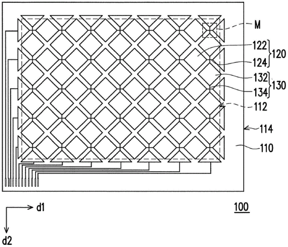
[0059] figure 1 It is a schematic top view of a touch panel according to an embodiment of the present invention. Please refer to figure 1 , the touch panel 100 includes a substrate 110, a plurality of first conductive units 120, a plurality of second conductive units 130, and a plurality of insulating patterns 140 (shown in figure 2 ). The substrate 110 includes a visible area 112 and a peripheral area 114 , wherein the peripheral area 114 is located on at least one side of the visible area 112 . In this embodiment, the peripheral area 114 surrounds the viewing area 112 . The first conductive unit 120 and the second conductive unit 130 are disposed on the substrate 110 and at least located in the visible area 112 . In other words, the first conductive unit 120 and the second conductive unit 130 may also extend to the peripheral area 114 . The peripheral area 114 is, for example, a non-visible area, and can be used to arrange signal wires, pads, or other components that a...


PUM


Abstract

The present invention provides a touch panel, comprising a substrate, a plurality of first conductive units, a plurality of second conductive units and a plurality of insulation patterns. Each first conductive unit comprises a plurality of first electrodes. Each second conductive unit comprises a plurality of second electrodes. Each first electrode comprises a first sub electrode and a second sub electrode which are stacked on the substrate in order. Each second electrode comprises a third sub electrode and a fourth sub electrode which are stacked on the substrate in order. The first sub electrodes and the third sub electrodes belong to a first conductive layer, and the second sub electrodes and the fourth sub electrodes belong to a second conductive layer. The first conductive layer has a plurality of differences. The differences are at least positioned at the boundaries of the first conductive units and the insulation patterns.

Description

technical field [0001] The present invention relates to a touch panel, and in particular to a touch panel with low conduction impedance and good touch sensing sensitivity. Background technique [0002] A capacitive touch panel usually includes a plurality of first conductive units arranged along a first direction (eg, vertical direction), and a plurality of second conductive units arranged along a second direction (eg, horizontal direction). The driver of the capacitive touch panel can output the driving signal to the first conductive unit, and receive the corresponding sensing signal generated by the second conductive unit, and then the capacitive touch panel generates a touch position signal correspondingly according to the received sensing signal . [0003] Generally speaking, the first sensing unit and the second sensing unit of the capacitive touch panel are formed of transparent conductive materials. However, the resistance value of the transparent conductive materia...

Claims


Application Information

Patent Timeline
Patent Type & Authority Applications(China)
IPC IPC(8): G06F3/044
Inventor 谢其铭蔡宜珍曾远康黄湘霖王文俊
Owner WINTEK CORP
Why Eureka
Try Eureka