
Alarm clock circuit and audio equipment

A circuit and alarm clock technology, applied in the electronic field, can solve the problems of alarm clock sounder losing power supply, unable to sound alarm clock reminder function, etc.

Inactive Publication Date: 2017-12-29
TCL TECH ELECTRONICS (HUIZHOU) CO LTD
View PDF6 Cites 0 Cited by
  • Summary
  • Abstract
  • Description
  • Claims
  • Application Information

AI Technical Summary

Problems solved by technology

[0003] Existing audio equipment with alarm clock reminder function must be in the case of plugging in the power supply (i.e. power-on state), when the time reaches the preset alarm clock time, the alarm clock sounder can make a sound to realize the automatic switch function of the alarm clock reminder However, in the case of not plugging in the power supply (i.e. not powered on), when the time reaches the preset alarm clock time, its alarm clock sounder cannot make a sound to realize the alarm clock reminder function due to the loss of power supply

Method used


Image

  • Alarm clock circuit and audio equipment
  • Alarm clock circuit and audio equipment

Examples


Embodiment Construction

[0026] It should be understood that the specific embodiments described here are only used to explain the present invention, not to limit the present invention.

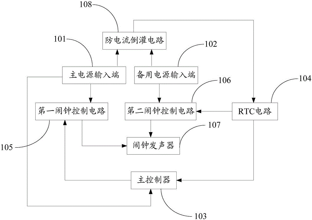
[0027] refer to figure 1 , figure 1 It is a schematic diagram of the module structure of an embodiment of the alarm clock circuit of the present invention.

[0028] The alarm clock circuit includes a main power input terminal 101, a standby power input terminal 102, a main controller 103, an RTC circuit 104, a first alarm clock control circuit 105, a second alarm clock control circuit 106, an alarm clock sounder 107 and an anti-current backflow circuit 108.

[0029] Wherein, the main power input terminal 101 is used for inputting main power.

[0030] The backup power input terminal 102 is used for inputting a backup power, which can be a button battery or a dry battery. In this embodiment, the voltage of the backup power input terminal 102 is equal to the voltage input by the main power input terminal 101;

[0031...


PUM


Abstract

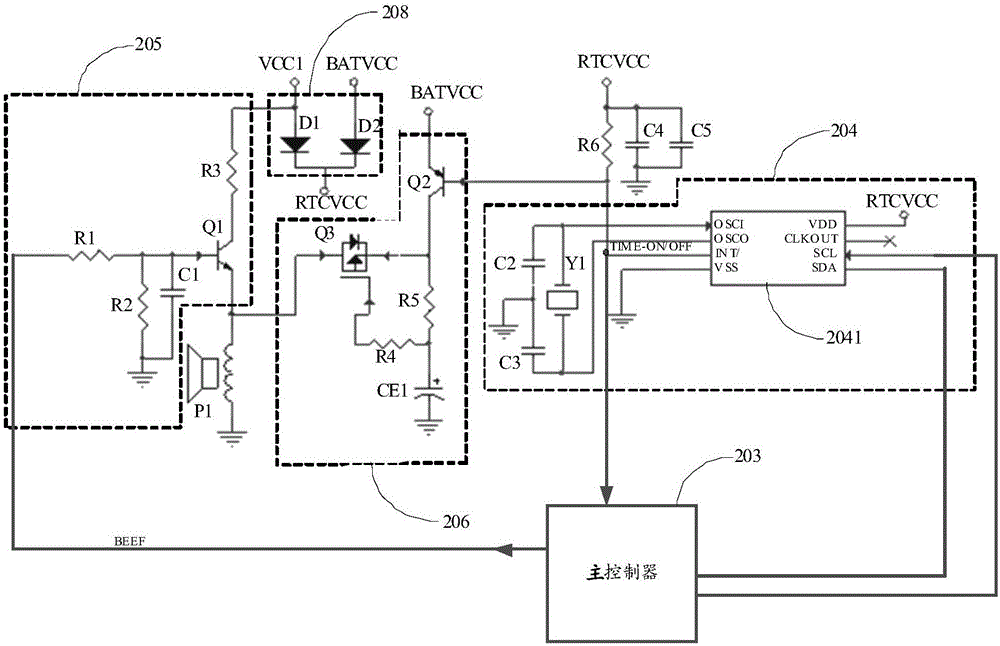
The present invention discloses an alarm clock circuit. The alarm clock circuit comprises an input end of a main power supply, an input end of a standby power, a main controller, a RTC circuit, a first alarm clock control circuit and a second alarm clock control circuit. The input end of the power supply of the first alarm clock control circuit is connected with the input end of the main power supply; the input end of the power supply of the second alarm clock control circuit is connected with the input end of the standby power; the input end of the power supply of the RTC circuit is connected with the input end of the standby power; the interception output end of the RTC circuit, the main controller and the control input end of the second alarm clock control circuit are connected with each other; the control output end of the main controller is connected with the control input end of the first alarm clock control circuit; and the control output ends of the first alarm clock control circuit and the second alarm clock control circuit are connected with the sounder of the alarm clock. The present invention further discloses a sound device. According to the invention, automatic switching of alarm clock reminds may be realized in the condition that a main power supply is not energized.

Description

technical field [0001] The invention relates to the field of electronic technology, in particular to an alarm clock circuit and audio equipment. Background technique [0002] At present, there are more and more types of audio equipment, and the functions of the audio equipment are also more and more personalized, although there are also many audio equipment with alarm clock reminder function on the current market. [0003] Existing audio equipment with alarm clock reminder function must be in the case of plugging in the power supply (i.e. power-on state), when the time reaches the preset alarm clock time, the alarm clock sounder can make a sound to realize the automatic switch function of the alarm clock reminder However, in the case of not plugging in the power supply (i.e. not powered on), when the time reaches the preset alarm clock time, its alarm clock sounder cannot sound to realize the alarm clock reminder function due to the loss of the power supply. Contents of th...

Claims


Application Information

Patent Timeline
Patent Type & Authority Patents(China)
IPC IPC(8): G05B19/04H04R3/00
Inventor 倪世坤余文才
Owner TCL TECH ELECTRONICS (HUIZHOU) CO LTD
Learn More