MIMO radar waveform design method for improving STAP detection performance

A MIMO-OFDM and radar waveform technology is applied in the field of MIMO-OFDM radar waveform design to improve STAP detection performance, and can solve problems such as data processing only at the receiving end

Active Publication Date: 2016-02-10
DALIAN UNIV
View PDF8 Cites 14 Cited by
  • Summary
  • Abstract
  • Description
  • Claims
  • Application Information

AI Technical Summary

Problems solved by technology

[0005] Although B.Friedlander and C.Y.Chen improved the detection performance of MIMO radar by optimizing the transmission waveform, they did not ap

Method used


Image

  • MIMO radar waveform design method for improving STAP detection performance
  • MIMO radar waveform design method for improving STAP detection performance
  • MIMO radar waveform design method for improving STAP detection performance

Examples


Embodiment Construction

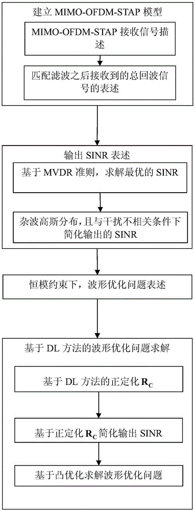
[0074] Attached below figure 2 The implementation steps of the present invention are further described in detail:

[0075] 1. MIMO-OFDM-STAP system modeling

[0076] (1) MIMO-OFDM-STAP received signal description

[0077] For the nth receiving element of MIMO-OFDM radar, the received data in the lth PRI can be expressed as:

[0078] x n , l = Σ m = 0 M - 1 ρ t s m e ...


PUM


Abstract

The invention belongs to the signal processing field, and relates to an MIMO-OFDM (Orthogonal Frequency Division Multiplexing) radar waveform design method for improving STAP detection performance. Under the constraint of a constant modulus, and based on an output SINR maximization criterion, the invention introduces the optimization problem of maximizing detection performance through designing emission waveforms. In order to solve a complex nonlinear optimization problem, the invention converts the nonlinear optimization problem into a semi-definite programming problem for obtaining an efficient solution based on a DL method, so as to maximize an output SINR, and thereby maximize system detection performance. The simulation result shows that compared with non-relevant emission waveforms, the emission waveforms obtained by the method can substantially increase an output SINR, thereby improving system detection performance. The method can obtain obviously improved detection performance compared with utilizing non-relevant waveforms.

Description

technical field [0001] The invention belongs to the field of signal processing, and relates to a method for designing MIMO-OFDM radar waveforms for improving STAP detection performance. This method can improve the signal-to-noise ratio at the output. By establishing the MIMO-OFDM-STAP model, under the constant modulus constraint, based on the output signal-to-noise ratio (SINR) maximization criterion, the design of the transmit waveform to maximize the detection performance is derived. optimization problem. Background technique [0002] Affected by the vigorous development of MIMO communication, and the need for new theories and new technologies for radar to break through its own limitations, the concept of MIMO radar came into being. Compared with phased-array radars, which can only transmit coherent waveforms, MIMO radars can utilize multiple transmitting units to transmit almost arbitrary waveforms. Based on the array antenna spacing, MIMO radar systems can be divided i...

Claims


Application Information

Patent Timeline
IPC IPC(8): G01S13/88G06F17/50
CPCG01S13/88G06F30/367
Inventor 王洪雁裴炳南王雪
Owner DALIAN UNIV
Why Eureka
Try Eureka