
vertical indoor unit

An indoor unit and vertical technology, applied in the field of vertical indoor units, can solve the problems of small air guide area and unfavorable air diffusion, and achieve the effect of large sweeping angle

Active Publication Date: 2017-12-05
WUHU MATY AIR CONDITIONING EQUIP CO LTD
View PDF8 Cites 0 Cited by
  • Summary
  • Abstract
  • Description
  • Claims
  • Application Information

AI Technical Summary

Problems solved by technology

However, such a swinging air guide covers a small area of ​​the air guide, making the direction of the air outlet more concentrated, which is not conducive to the diffusion of air.

Method used


Image

  • vertical indoor unit
  • vertical indoor unit
  • vertical indoor unit

Examples


Embodiment Construction

[0028] It should be understood that the specific embodiments described here are only used to explain the present invention, not to limit the present invention.

[0029] It should be understood that the specific embodiments described here are only used to explain the present invention, not to limit the present invention.

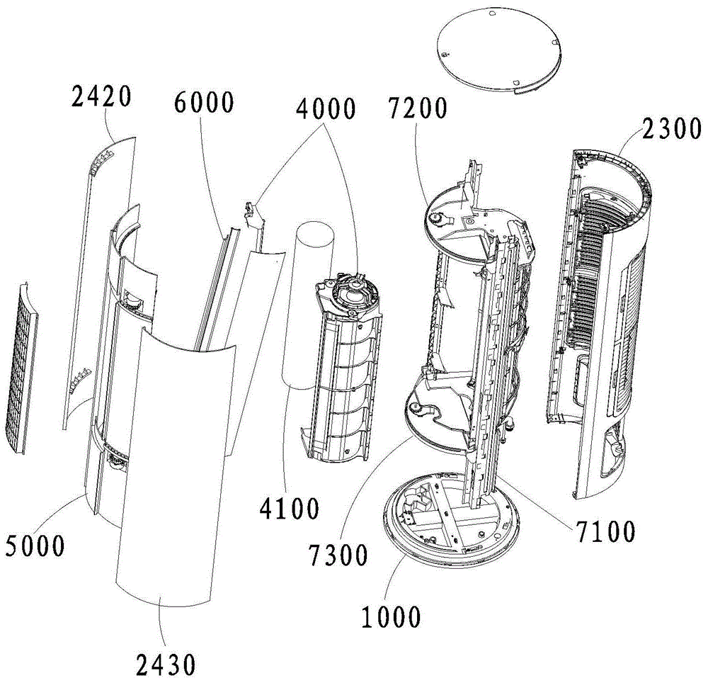
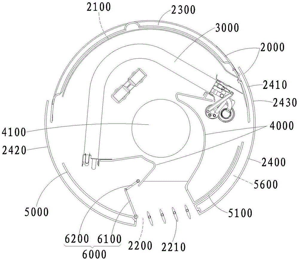
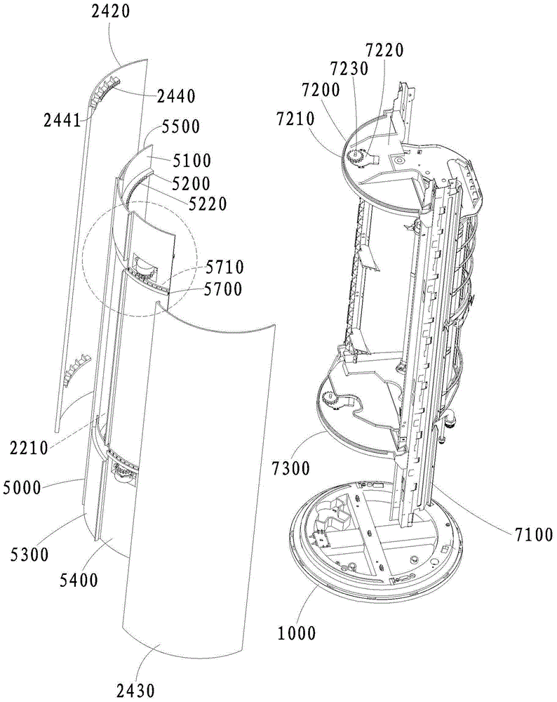
[0030] Usually the vertical indoor unit includes a shell, which is provided with an air inlet and an air outlet, and an evaporator is fixed between the air inlet and the air outlet in the housing, and the air will pass through the fins of the evaporator after entering from the air inlet. And blow out from the air outlet. When the evaporator is working, the temperature on its surface will change, and the air flowing through its surface will also be affected, so as to achieve the effect of adjusting the temperature of the outlet air. A volute tongue assembly is arranged between the evaporator and the air outlet to form an air passage connecting the evaporator ...


PUM


Abstract

The invention discloses a vertical type indoor unit. The vertical type indoor unit comprises a shell body arranged on a machine body fixing base. Air inlets and air outlets are formed in the shell body. The strip-shaped air outlets extend longitudinally. An evaporator, a volute and volute tongue assembly and an air outlet frame are sequentially arranged from the air inlets to the air outlets. A cross-flow wind wheel extending longitudinally is arranged in the volute and volute tongue assembly. The air outlet frame is connected between the volute and volute tongue assembly and the air outlets and is used for forming air channels communicating the air inlets with the air outlets. A driving device is further arranged in the shell body. The driving device drives the air outlet frame to rotate back and forth around a rotation axis parallel to the axis of the cross-flow wind wheel. Each air channel is provided with two longitudinal side walls parallel to the axis of the cross-flow wind wheel. The air outlet frame abuts against the volute and volute tongue assembly to form at least one longitudinal side wall. According to the vertical type indoor unit, the effect that the cover area of swing wind guiding is larger is achieved.

Description

technical field [0001] The invention relates to the field of household appliances, in particular to a vertical indoor unit. Background technique [0002] The existing single cross-flow vertical air conditioner usually only achieves the effect of swinging the wind left and right through the left and right swing of the longitudinal guide vanes at the air outlet. However, such a swinging air guiding area covers a relatively small air guiding area, so that the air outlet direction is more concentrated, which is not conducive to the diffusion of air. Contents of the invention [0003] The main purpose of the present invention is to provide a single through-flow cabinet air conditioner, aiming at increasing the coverage area of ​​the swinging air guide. [0004] In order to achieve the above object, the present invention provides a vertical indoor unit, the vertical indoor unit includes a housing installed on the body fixing seat, the housing is formed with an air inlet and an ...

Claims


Application Information

Patent Timeline
Patent Type & Authority Patents(China)
IPC IPC(8): F24F1/00F24F13/10F24F13/14
CPCF24F1/0007F24F13/10F24F13/1413F24F13/1426F24F2013/1433
Inventor 毛先友万明
Owner WUHU MATY AIR CONDITIONING EQUIP CO LTD
Learn More