Elevator traction machine

A technology of elevator traction machine and traction wheel, applied in the field of elevator traction machine, can solve problems such as poor braking effect, unfavorable safe use, inconvenient maintenance, etc., and achieve the effect of avoiding abnormalities

Inactive Publication Date: 2016-02-10
CHONGQING ENERGY COLLEGE
View PDF0 Cites 0 Cited by
  • Summary
  • Abstract
  • Description
  • Claims
  • Application Information

AI Technical Summary

Problems solved by technology

However, the current traction machine has the disadvantages of poor braking effect, easy wear and failure of the brake, which is not conducive to safe use and inconvenient maintenance.

Method used


Image

  • Elevator traction machine
  • Elevator traction machine

Examples


Embodiment Construction

[0014] In order to make the technical means, creative features, goals and effects achieved by the present invention easy to understand, the present invention will be further described below in conjunction with specific embodiments.

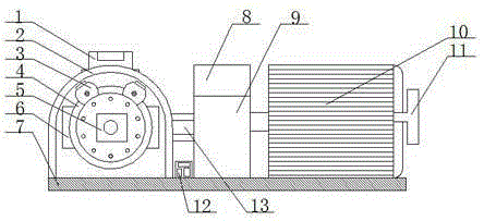
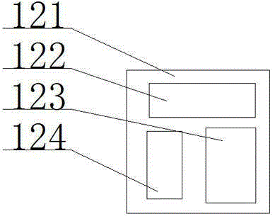
[0015] see figure 1 with figure 2 , the present invention provides a technical solution: an elevator traction machine, including a brake shoe controller 1, a brake shoe 3, an emergency brake 6 and a control box 12, and the brake shoe controller 1 is installed on the top of the base 2 , a traction sheave 4 is arranged in the machine base 2, and the machine base 2 and the traction sheave 4 are connected by bearings, the brake shoe 3 is arranged above the traction sheave 4, and the brake shoe 3 and the brake shoe controller 1 Electrically connected, two brake shoes 3 are provided, and the two brake shoes 3 are installed above the traction sheave 4, the traction sheave 4 is provided with a turbine controller 5, and the emergency brake 6 is installed...


PUM


Abstract

The invention provides an elevator traction machine. The elevator traction machine comprises a brake shoe controller, brake shoes, emergency brakes and a control cabinet. The brake shoe controller is installed on the top of a machine base, a traction wheel is arranged in the machine base, the machine base is connected to the traction wheel through a bearing, the brake shoes are arranged above the traction wheel and are electrically connected with the brake shoe controller, the traction wheel is provided with a wheel machine controller, and the emergency brakes are installed on the traction wheel. The machine base is installed on a bottom plate, a speed change box is arranged on the right side of the machine base, a brake is arranged above the speed change box, the control cabinet is installed between the machine base and the speed change box, and a traction motor is arranged on the right side of the speed change box. Compared with the prior art, the elevator traction machine has the advantages of being convenient to use and high in safety and realizing effective braking through the brakes so as to guarantee the personnel safety and the property safety under special circumstances during elevator operation.

Description

technical field [0001] The invention is an elevator traction machine, which belongs to the field of elevator mechanical equipment. Background technique [0002] The elevator traction machine is the power equipment of the elevator, also known as the elevator host. The function is to convey and transmit power to make the elevator run. It is composed of motor, brake, coupling, reduction box, traction wheel, frame, guide wheel and auxiliary turning hand wheel. The guide wheels are generally installed on the frame or the load-bearing beam under the frame. Some of the turning hand wheels are fixed on the motor shaft, and some are usually hung on the nearby wall, and then set on the motor shaft when in use. However, the current traction machine has the disadvantages of poor braking effect, easy wear and failure of the brake, which is not conducive to safe use and inconvenient maintenance. Contents of the invention [0003] Aiming at the deficiencies in the prior art, the purp...

Claims


Application Information

Patent Timeline
Patent Type & Authority Applications(China)
IPC IPC(8): B66B11/04
Inventor 司良群
Owner CHONGQING ENERGY COLLEGE
Why Eureka
Try Eureka