Pneumatic braking system of rubber tire low-floor intelligent rail train

A rail train, air brake technology, applied in the direction of brakes, brake components, brake transmission devices, etc., can solve the problems of early brake response, long brake response time, long air pressure and airflow transmission time, etc. The effect of reduced response time, convenient maintenance of the overall structure, and reasonable pipeline layout

Active Publication Date: 2018-10-26
HUNAN CRRC INTELLIGENT TRANSPORT TECH CO LTD +1
View PDF8 Cites 0 Cited by
  • Summary
  • Abstract
  • Description
  • Claims
  • Application Information

AI Technical Summary

Problems solved by technology

The pneumatic brake system has its unique advantages, such as: 1. The brake pedal force is small and the stroke is small; 2. It can generate a large braking force; 3. The pipeline structure is simple and easy to connect and disconnect. The braking system also has disadvantages. Due to its own structure, the disadvantage is that the braking response time is long. As the length of the vehicle increases (for example: car train), the braking response time will also increase, and its impact will become more and more serious. obvious
Because the brake operating device and the actuator are connected and controlled through the air pipeline, the transmission time of the air pressure airflow of about 0.8MPa is long. In order to solve this problem, the current common solution is to add a relay valve, a quick release valve, and a trailer Valves and other devices make the braking response earlier. This solution is more effective for commercial vehicles with a length of less than 18 meters, but the effect is not good for multi-axle vehicles longer than 18 meters.

Method used


Image

  • Pneumatic braking system of rubber tire low-floor intelligent rail train

Examples


Embodiment Construction

[0017] The present invention will be further described in detail below in conjunction with the accompanying drawings and specific embodiments.

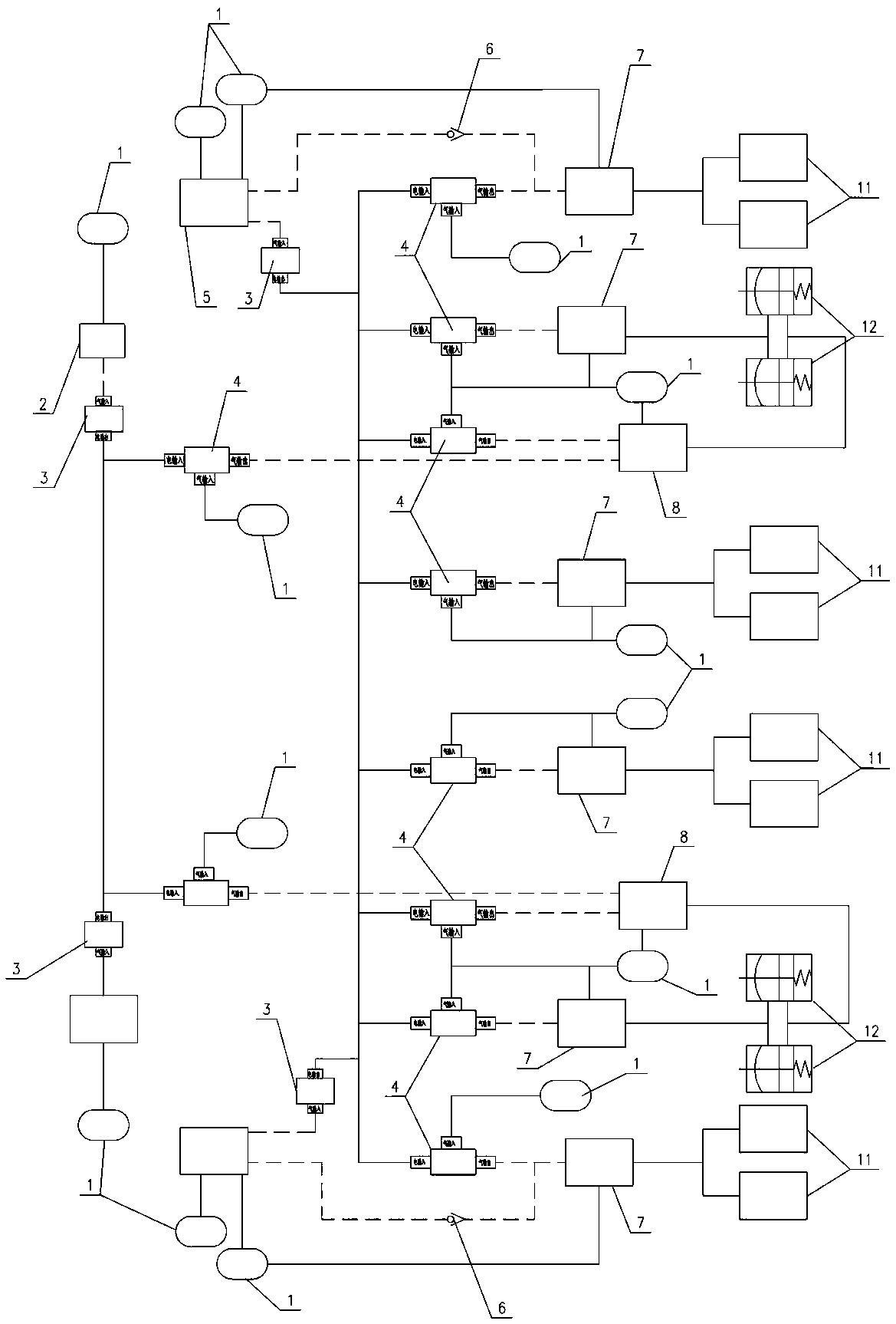
[0018] like figure 1 Shown, the pneumatic braking system of the rubber tire low-floor intelligent rail train of the present invention comprises hand valve 2, main valve 5 (as: brake pedal), air reservoir 1, solenoid valve, check valve 6, air chamber and It is used to connect the wiring harness of the above-mentioned devices to form an air supply air circuit and a control air circuit; in the present invention, in the foot brake circuit, a first signal switching solenoid valve (such as: air-to-electric solenoid valve 3) is set after the main valve 5; When there is an air flow input, the air-to-electric solenoid valve 3 will generate electrical signals with different current intensities according to the air pressure, and the electrical signals will be transmitted to the relay solenoid valve 7, and the relay solenoid valve 7 will distribu...


PUM


Abstract

The invention discloses an air braking system of a rubber wheel low-floor intelligent rail train. The system comprises a hand valve, a main valve, an air reservoir, an air chamber and a wire harness, wherein the wire harness is used for connecting the devices to form an air supply air path and a control air path. In a foot braking loop, a first signal conversion electromagnetic valve is arranged behind the main valve. When air flow is input, an air-to-electricity type electromagnetic valve generates electric signals with different current strengths according to the airflow air pressure, the electric signals are transmitted to a relay electromagnetic valve, and the relay electromagnetic valve distributes airflow of different air pressures to the relay valve control connector according to the electric signal input magnitude. The air braking system has the advantages of being simple and compact in structure, low in cost, high in control accuracy and the like.

Description

technical field [0001] The invention mainly relates to the field of urban public transportation equipment, in particular to an air pressure braking system for rubber-tyred low-floor intelligent rail trains. Background technique [0002] Urban rail transit refers to a special-line public transportation system with continuous guiding capabilities, which is characterized by having a specific track and vehicles running along the track. Common urban rail transit includes subways, light rails, and trams. Among them, subways and light rails are mostly built underground or on viaducts, and they can run freely in special rail lines by using the blocking mode. Although they have a strong transportation capacity, the initial infrastructure and vehicle purchase costs are relatively high, making them unavailable in small and medium-sized cities. application. Trams require a special power system and track coordination design, whether the design and construction costs or maintenance cost...

Claims


Application Information

Patent Timeline
Patent Type & Authority Patents(China)
IPC IPC(8): B60T13/68B60T15/04B60T15/12
CPCB60T13/683B60T15/048B60T15/12
Inventor 翁涛杨勇陈标李泽波周宏涛朱田陈煌熙任田良
Owner HUNAN CRRC INTELLIGENT TRANSPORT TECH CO LTD
Why Eureka
Try Eureka