Low drift reference for laser radar

A reference beam, laser ranging technology, applied in the direction of using re-radiation, re-radiation of electromagnetic waves, measuring devices, etc., can solve problems such as huge cost and distance calibration drift

Active Publication Date: 2016-02-03
NIKON METROLOGY
View PDF15 Cites 17 Cited by
  • Summary
  • Abstract
  • Description
  • Claims
  • Application Information

AI Technical Summary

Problems solved by technology

The useful beam scan rate can be limited by the encoder rate, and the distance cali

Method used


Image

  • Low drift reference for laser radar
  • Low drift reference for laser radar
  • Low drift reference for laser radar

Examples


Embodiment Construction

[0082] As used in this application and in the claims, the singular forms "a" and "the" include plural referents unless the context clearly dictates otherwise. Also, the term "comprising" means "comprising". Furthermore, the term "coupled" does not exclude the presence of intervening elements between the coupled items.

[0083] The systems, devices and methods described herein should not be construed as limiting in any way. Rather, the present disclosure is directed to all novel and non-obvious features and aspects of the various disclosed embodiments both individually and in various combinations and subcombinations. The disclosed systems, methods and apparatus are neither limited to any particular aspect or feature or combination thereof, nor do the disclosed systems, methods and apparatus require that any one or more particular advantages exist or problems be solved. Any theories of operation are provided as an aid to explanation, but the disclosed systems, methods and devi...


PUM


Abstract

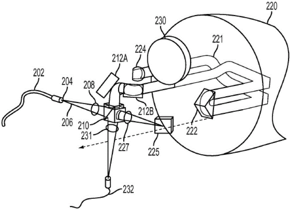
Laser radar systems include a pentaprism configured to scan a measurement beam with respect to a target surface. A focusing optical assembly includes a corner cube that is used to adjust measurement beam focus. Target distance is estimated based on heterodyne frequencies between a return beam and a local oscillator beam. The local oscillator beam is configured to propagate to and from the focusing optical assembly before mixing with the return beam. In some examples, heterodyne frequencies are calibrated with respect to target distance using a Fabry-Perot interferometer having mirrors fixed to a lithium aluminosilicate glass-ceramic tube.

Description

[0001] Cross References to Related Applications [0002] This application claims U.S. Provisional Application 61 / 728,999, filed November 21, 2012; U.S. Provisional Application 61 / 753,786, filed January 17, 2013; Interest, these applications are incorporated herein by reference. technical field [0003] The present disclosure relates to lidar systems. Background technique [0004] LiDAR systems provide simple, convenient, non-contact measurements that facilitate single-operator object inspection. LiDAR systems are especially useful for applications where large objects such as aircraft, automobiles, wind turbines or satellite components are to be measured. Some conventional lidar systems are described in US Patents 4,733,609, 4,824,251, 4,830,486, 4,969,736, 5,114,226, 7,139,446, 7,925,134, US Patent Application Publication 2011 / 0205523, and Japanese Patent 2,664,399, which are incorporated herein by reference. In these lidar systems, a laser beam is directed and scanned ov...

Claims


Application Information

Patent Timeline
IPC IPC(8): G01S7/481G01S7/491G01S17/32G01S17/89G01S7/497G01S17/34
CPCG01S17/89G01S7/4812G01S7/491G01S7/497G01S17/34G01C3/08
Inventor A·R·斯朗特文斯基M·A·里兹克
Owner NIKON METROLOGY
Why Eureka
Try Eureka