
Active power factor correction circuit system

A technology for correcting circuit and source power, applied in output power conversion devices, electrical components, high-efficiency power electronic conversion, etc. High factor and power factor value, the effect of preventing high frequency transient impact

Inactive Publication Date: 2016-02-03
JIANGSU LVYANG ELECTRONICS INSTR GROUP
View PDF3 Cites 0 Cited by
  • Summary
  • Abstract
  • Description
  • Claims
  • Application Information

AI Technical Summary

Problems solved by technology

Higher harmonics will cause harm to the power grid, the power factor of the input end of the electrical equipment will drop, and strong electromagnetic interference (EMI) will be generated, which will cause potential harm to the safe operation of the grid and other electrical equipment

Method used


Image

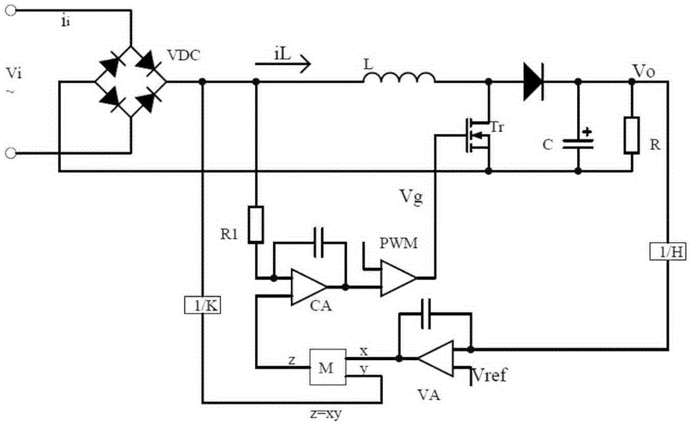
  • Active power factor correction circuit system
  • Active power factor correction circuit system
  • Active power factor correction circuit system

Examples


Embodiment Construction

[0016] Below in conjunction with embodiment the content of the present invention is further described.

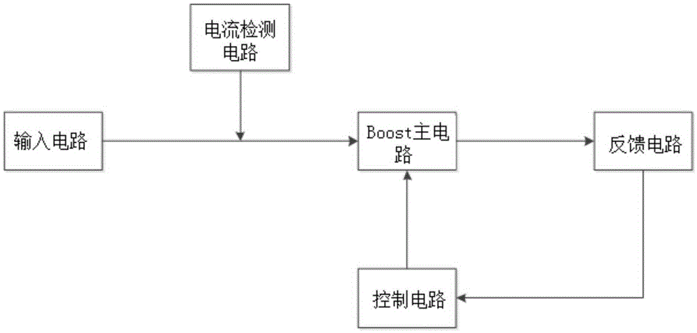
[0017] The active power factor correction circuit system includes an input circuit, a current detection circuit, a Boost main circuit, a feedback circuit and a control circuit; the input circuit and the current detection circuit are connected to the Boost main circuit, and the Boost main circuit is connected to the feedback circuit, The feedback circuit is connected with the control circuit, and the control circuit is connected with the Boost main circuit.

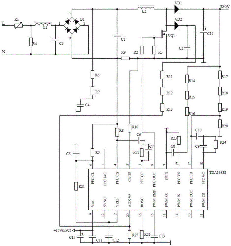
[0018] The active power factor correction circuit system includes resistors R1-R25, capacitors C1-C15, inductors L1 and L2, rectifier bridge B1, diodes VD1 and VD2, switch tube VQ1, controller, 380V power supply and 15V power supply; resistor R1 The common end of the resistor R4 and R4 is connected to one end of the inductor L1, the other end of the resistor R4 is connected to the other end of the inductor L1 after the ...


PUM


Abstract

The invention belongs to the field of power electronic technologies, and particularly relates to an active power factor correction circuit system. The active power factor correction circuit system comprises an input circuit, a current detection circuit, a Boost main circuit, a feedback circuit and a control circuit, and is characterized in that the input circuit and the current detection circuit are connected with the Boost main circuit, the Boost main circuit is connected with the feedback circuit, the feedback circuit is connected with the control circuit, and the control circuit is connected with the Boost main circuit. The active power factor correction circuit system provided by the invention is high in efficiency, capable of improving the adaptability of a power supply, simple in boost APFC (active power factor correction) control, wide in applicable power range and capable of effectively improving a power factor of a circuit.

Description

technical field [0001] The invention belongs to the technical field of power electronics, in particular to an active power factor correction circuit system. Background technique [0002] At present, the power front stage of household appliances mostly adopts the diode full-bridge rectification method, which will cause harmonic pollution to the power grid, lower power factor, and the reactive components are mainly high-order harmonics, of which the amplitude of the third harmonic is about 95% of the amplitude of the fundamental wave. , the fifth harmonic amplitude is about 70% of the fundamental amplitude. The seventh harmonic amplitude is approximately 45% of the fundamental amplitude. High-order harmonics will cause harm to the power grid, the power factor of the input terminal of the electrical equipment will drop, and strong electromagnetic interference (EMI) will be generated, which will cause potential harm to the safe operation of the grid and other electrical equipme...

Claims


Application Information

Patent Timeline
Patent Type & Authority Applications(China)
IPC IPC(8): H02M1/42H02M1/44
CPCY02B70/10
Inventor 颜于凤马金科
Owner JIANGSU LVYANG ELECTRONICS INSTR GROUP
Learn More