Power transformer high voltage winding without generating partial discharge
A technology for power transformers and high-voltage windings, which is applied in the manufacture of inductors/transformers/magnets, circuits, and electrical components. Requirements and process to achieve difficulty, the effect of increased service life
- Summary
- Abstract
- Description
- Claims
- Application Information
AI Technical Summary
Problems solved by technology
Method used
Image
Examples
Embodiment 1
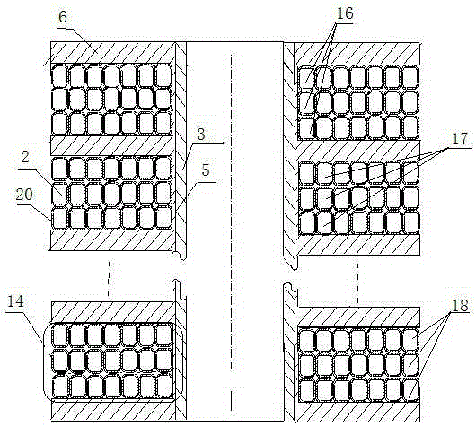
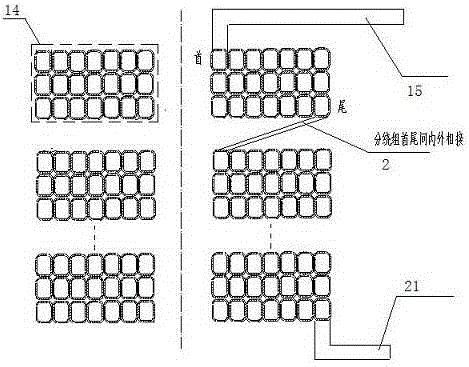
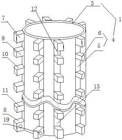
[0023] A high-voltage winding of a power transformer that does not generate partial discharge, including a winding frame 1 and a wire 2, the winding frame 1 includes an inner lining cylinder 3 and several comb-shaped racks 4, and the comb-shaped racks 4 are longitudinally fixed to the inner lining cylinder 3 On the outer wall of the comb rack 4, the comb rack 4 includes a rack 5 and a positioning tooth set 6, and the positioning tooth set 6 includes an incoming line positioning tooth 7 fixed on the top of the rack, an outgoing line positioning tooth 8 fixed on the bottom end of the rack, and The first main positioning tooth 9, the second main positioning tooth 10, ..., the n1th main positioning tooth 11 (n1 is a positive integer) are located between the incoming line positioning tooth and the outgoing line positioning tooth; the incoming line positioning on the same comb rack A first tooth slot 12 is formed between the tooth and the adjacent main positioning tooth, a second too...
Embodiment 2
[0032] A high-voltage winding of a power transformer that does not generate partial discharge, including a winding frame 1 and a wire 2, the winding frame 1 includes an inner lining cylinder 3 and several comb-shaped racks 4, and the comb-shaped racks 4 are longitudinally fixed to the inner lining cylinder 3 On the outer wall of the comb rack 4, the comb rack 4 includes a rack 5 and a positioning tooth set 6, and the positioning tooth set 6 includes an incoming line positioning tooth 7 fixed on the top of the rack, an outgoing line positioning tooth 8 fixed on the bottom end of the rack, and The first main positioning tooth 9, the second main positioning tooth 10, ..., the n1th main positioning tooth 11 (n1 is a positive integer) are located between the incoming line positioning tooth and the outgoing line positioning tooth; the incoming line positioning on the same comb rack A first tooth slot 12 is formed between the tooth and the adjacent main positioning tooth, a second too...
PUM
| Property | Measurement | Unit |
|---|---|---|
| thickness | aaaaa | aaaaa |
| thickness | aaaaa | aaaaa |
Abstract
Description
Claims
Application Information
 - R&D Engineer
- R&D Manager
- IP Professional
- Industry Leading Data Capabilities
- Powerful AI technology
- Patent DNA Extraction
Browse by: Latest US Patents, China's latest patents, Technical Efficacy Thesaurus, Application Domain, Technology Topic, Popular Technical Reports.
© 2024 PatSnap. All rights reserved.Legal|Privacy policy|Modern Slavery Act Transparency Statement|Sitemap|About US| Contact US: help@patsnap.com


