
MOEMS scanning raster micromirror system

A technology of grating micromirror and scanning grating, which is applied in the field of MEMS scanning grating micromirror, which can solve the problems of small angle output signal, weak angle output signal, and easy wear of mechanical shaft, so as to improve angle output signal, increase driving voltage, and reduce The effect of resistance value

Active Publication Date: 2016-02-03
CHONGQING UNIV
View PDF5 Cites 15 Cited by
  • Summary
  • Abstract
  • Description
  • Claims
  • Application Information

AI Technical Summary

Problems solved by technology

Since there is no integrated angle sensor, there are obvious problems in this system: the scanning speed of the stepping motor is slow, the repeatability of the system output spectrum wavelength is poor, especially the mechanical shaft of the second integrated stepping motor is easy to wear
The disadvantages of this design are: firstly, the rectangular design of the MOEMS scanning grating micromirror, driving coil and angle sensor not only increases the manufacturing cost, but also cannot achieve the maximum angle output signal under the premise of a certain area no matter how the sensing coil is designed. Secondly, the ratio optimization design of the angle sensing coil and the driving coil has not been carried out. The integrated angle sensor has only one circle and the angle output signal is very small, only in the order of several millivolts, so the angle output signal is very small, and the noise is basically In an order of magnitude, it is difficult to be collected by the back-end circuit
It can be seen that the previously designed MOEMS scanning grating with integrated angle sensor initially integrated the angle sensor on the MOEMS scanning grating micromirror, but due to the deficiencies in the design, the angle output signal is weak and difficult to collect, so it is impossible to accurately control the MOEMS scanning grating. Micromirror scanning angle and range

Method used


Image

  • MOEMS scanning raster micromirror system
  • MOEMS scanning raster micromirror system
  • MOEMS scanning raster micromirror system

Examples


Embodiment Construction

[0024] The present invention will be further described below in conjunction with accompanying drawing.

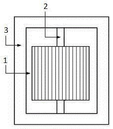
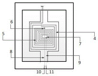
[0025] see figure 1 and figure 2 , MOEMS scanning grating micromirror of the present invention is a square, and it is made of scanning grating 1, torsion beam 2, fixed frame 3, drive coil 4, angle sensing coil 5, outer end open line 6, inner end open line 7, buried Layer leads 8, 9, electrodes 10, 11 are jointly integrated on the same single crystal silicon substrate through MEMS processing technology.

[0026] Among them, the scanning grating 1, the torsion beam 2, and the fixed frame 3 are integrated on the front of the silicon substrate. The torsion beam 2 connects the scanning grating 1 and the fixed frame 3. The torsion beam 2 can drive the entire MOEMS scanning grating under the drive of the driving coil 4. The micromirror rotates around it, and the fixed frame 3 supports and fixes it. On the front side of the MOEMS scanning grating micromirror, a scanning grating...


PUM


Abstract

Provided is an MOEMS scanning raster micromirror system, comprising an MOEMS scanning raster micromirror and a rear end closed loop control circuit. The MOEMS scanning raster micromirror employs a square design, and mainly comprises a scanning raster, a torsion beam, a fixing frame, an electromagnetic driver and a magneto-electric angle sensor which are three-dimensionally integrated on a monocrystalline silicon piece through the MEMS processing technology. The magneto-electric angle sensor is in a square shape and employs a multiturn gradually open design with a surface layer gold-plated. The MOEMS scanning raster micromirror and the magneto-electric angle sensor meanwhile employ a square design, and can guarantee that the MOEMS scanning raster micromirror generates real time and dynamic greatest angle output signals in a scanning process. Meanwhile, the electromagnetic driver and the magneto-electric angle sensor employ an optimum turn ratio design, thereby realizing maximum angle output signals under the condition of low-voltage driving the MOEMS scanning raster micromirror to scan. The rear end closed loop control circuit can accurately control the MOEMS scanning raster micromirror. The MOEMS scanning raster micromirror system can be widely applied to micro spectrometers.

Description

technical field [0001] The invention relates to a MEMS scanning grating micromirror, and belongs to the fields of spectral analysis technology and MEMS technology. Background technique [0002] Scanning grating micromirror, as the core component of spectroscopic analysis instrument, has spectroscopic function. The MOEMS scanning grating micromirror, which integrates the grating (light splitting), micromirror (scanning) and angle sensor (micromirror motion detection) into a single chip, can not only achieve high control accuracy of the scanning grating micromirror, improve the accuracy of the spectrometer, but also Can reduce system structure and control difficulty. Faced with the current needs of many special environmental fields such as air pollution monitoring, food safety testing, and pharmaceutical ingredient testing, countries around the world have conducted in-depth research on how to precisely control scanning grating micromirrors. [0003] The series of spectromete...

Claims


Application Information

Patent Timeline
IPC IPC(8): G02B26/08G02B26/00G02B27/10G02B27/42
CPCG02B26/00G02B26/085G02B27/1086G02B27/4233
Inventor 温志渝周颖刘海涛
Owner CHONGQING UNIV
Learn More