
A state monitoring circuit of a circuit breaker with auxiliary contacts

A circuit breaker status and auxiliary contact technology, which is applied in circuit breaker testing and other directions, can solve problems such as high voltage and large current of the main contact, and achieve the effect of flexible use, low reliability and improved accuracy

Active Publication Date: 2019-12-17
SHANGHAI AVIATION ELECTRIC
View PDF4 Cites 0 Cited by
  • Summary
  • Abstract
  • Description
  • Claims
  • Application Information

AI Technical Summary

Problems solved by technology

[0009] In many cases, the current of the main contact of the circuit breaker is very large, or the voltage is very high, which cannot be directly used for detection, and must be replaced by an auxiliary contact

Method used


Image

  • A state monitoring circuit of a circuit breaker with auxiliary contacts
  • A state monitoring circuit of a circuit breaker with auxiliary contacts

Examples


Embodiment Construction

[0024] The present invention will be further described below in conjunction with the accompanying drawings and embodiments.

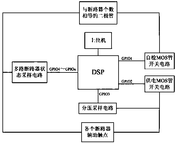
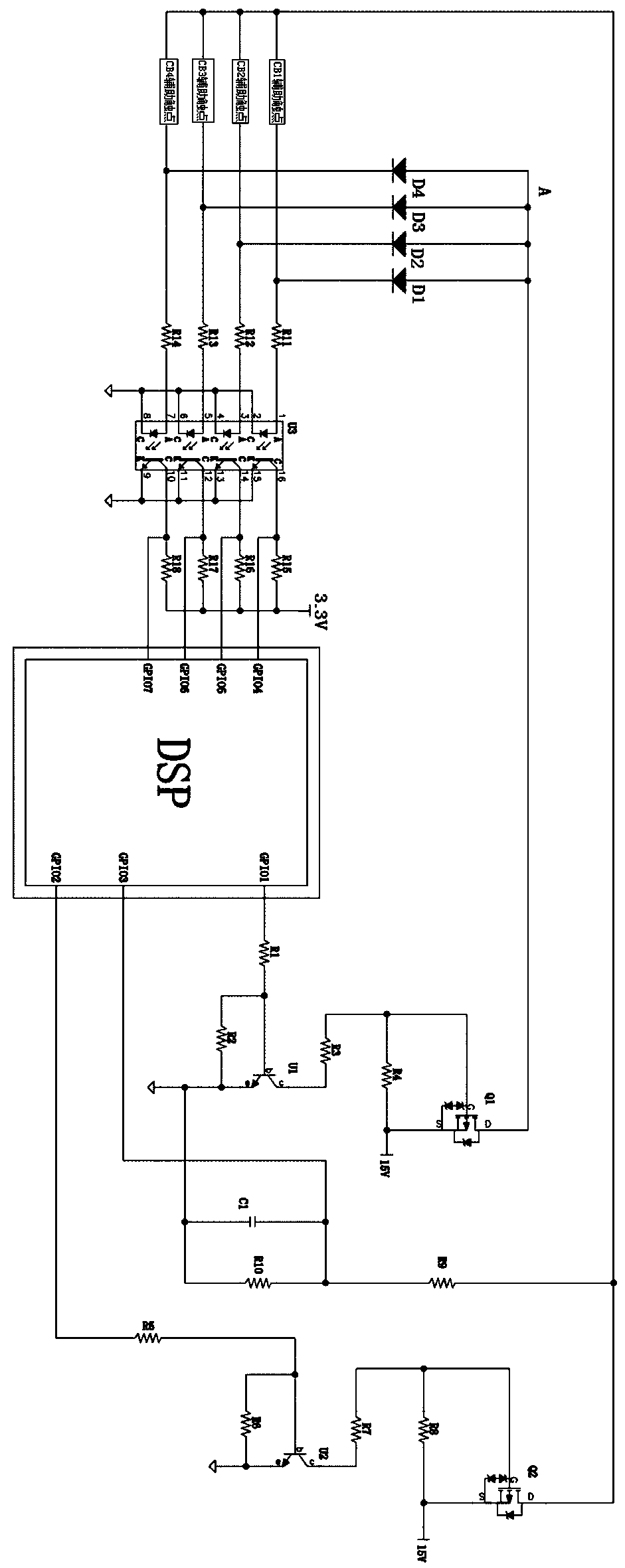
[0025] Such as figure 1 As shown, the present invention includes a host computer, a DSP (digital signal processor), a self-checking MOS tube switch circuit, a power supply MOS tube switch circuit, a voltage dividing sampling circuit, a multi-channel circuit breaker state sampling circuit, and a number equal to the number of circuit breakers Diodes, auxiliary contacts of each circuit breaker; the host computer is connected to the DSP, and the first output terminal GPIO1 of the DSP is sequentially connected to the self-test MOS tube switch circuit, diodes equal to the number of circuit breakers, and multi-circuit breaker state sampling circuits. The output of the circuit breaker state sampling circuit is connected to multiple sampling input terminals GPIO4~GPIOn of the DSP respectively; the second output terminal GPIO2 of the DSP is connected to the power...


PUM


Abstract

The invention discloses a state monitoring circuit for a breaker with auxiliary contacts. The state monitoring circuit comprises a host computer, a DSP (Digital Signal Processor), a self-check MOS (Metal Oxide Semiconductor) tube switch circuit, a power supply MOS tube switch circuit, a voltage division sampling circuit, a multipath breaker state sampling circuit, diodes with the same number of breakers, and various breaker auxiliary contacts. The DSP determines opening and closing states of each breaker by reading output signals of the multipath breaker state sampling circuit, and reports the opening and closing states of each breaker to the host computer. The self-check circuit is added in the multipath breaker state sampling circuit and the power supply MOS tube switch circuit for power-on self test or period self test, circuit faults can be eliminated, and accuracy of breaker state determination is ensured.

Description

technical field [0001] The invention relates to a state monitoring circuit of a circuit breaker with auxiliary contacts, which can be used to monitor the states of multiple circuit breakers, and the circuit can perform self-inspection or periodic self-inspection on the state monitoring circuit of the circuit breaker to reduce the failure rate. Background technique [0002] With the development of science and technology, in some high-tech fields, especially national defense, aviation and other fields, reliability has been paid more and more attention, and it is an important indicator to measure product quality. The purpose of self-inspection is mainly to improve the reliability of the system. Therefore, to improve product quality, the self-inspection ability of the system must be improved. [0003] Since the 1980s, self-inspection technology has developed rapidly abroad. Researchers have carried out a large number of researches on system testing and diagnosis problems. Testab...

Claims


Application Information

Patent Timeline
Patent Type & Authority Patents(China)
IPC IPC(8): G01R31/327
Inventor 江婷婷
Owner SHANGHAI AVIATION ELECTRIC
Learn More