
Target material structure of magnetic control splashing device

A magnetron sputtering device and target material technology, which is applied in sputtering plating, metal material coating process, ion implantation plating, etc., can solve the problem of reduced equipment driving rate, increased equipment maintenance frequency, and target utilization rate. low level problem

Inactive Publication Date: 2016-02-03
WUHAN CHINA STAR OPTOELECTRONICS TECH CO LTD
View PDF5 Cites 0 Cited by
  • Summary
  • Abstract
  • Description
  • Claims
  • Application Information

AI Technical Summary

Problems solved by technology

[0007] In view of this, the present invention provides a target structure of a magnetron sputtering device to solve the existing problems in the prior art such as low target utilization rate, increased equipment maintenance frequency, and reduced equipment driving rate.

Method used


Image

  • Target material structure of magnetic control splashing device
  • Target material structure of magnetic control splashing device
  • Target material structure of magnetic control splashing device

Examples


Embodiment Construction

[0026] The following descriptions of the various embodiments refer to the accompanying drawings to illustrate specific embodiments in which the present invention can be practiced. Furthermore, the directional terms mentioned in the present invention are, for example, up, down, top, bottom, front, back, left, right, inside, outside, side, surrounding, central, horizontal, transverse, vertical, longitudinal, axial, The radial direction, the uppermost layer or the lowermost layer, etc. are only directions referring to the attached drawings. Therefore, the directional terms used are used to illustrate and understand the present invention, but not to limit the present invention.

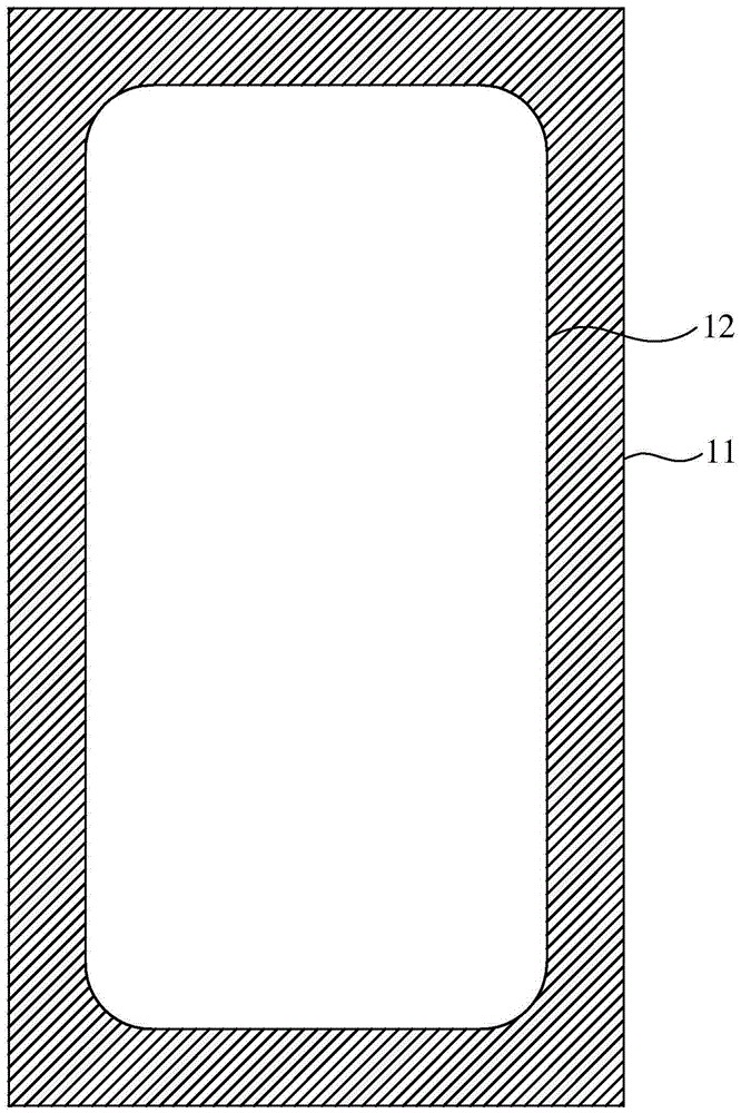
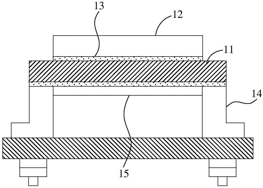
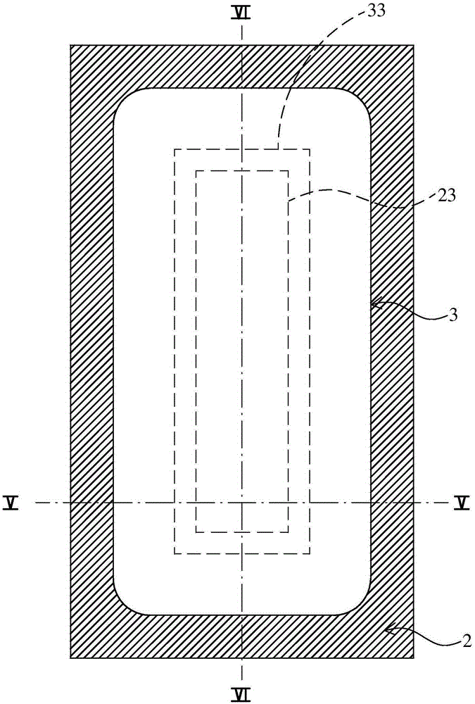
[0027] Please refer to image 3 and 4 As shown, it is a preferred embodiment of the target structure of the magnetron sputtering device of the present invention, wherein the target structure 100 of the magnetron sputtering device is arranged on a target holder 101, and is located in the magnetron sputte...


PUM

PropertyMeasurementUnit
thicknessaaaaaaaaaa

Abstract

The invention discloses a target material structure of a magnetic control splashing device. The target material structure comprises a back plate, a target material and an adhesion layer. The back plate comprises a front end face, a rear end face and a protruding part. The target material comprises a cooling surface, a splashing surface and a concave part. The cooling surface is arranged on the front end face of the back plate. The splashing surface is opposite to the cooling surface. The concave part is arranged on the cooling surface and used for being combined with the protruding part. Due to the design of the protruding part and the concave part, the thickness of the edge of the target material is increased, the service time of the edge of the target material can be prolonged, and the service life of the target material is prolonged.

Description

technical field [0001] The invention relates to a target structure, in particular to a target structure of a magnetron sputtering device. Background technique [0002] Thanks to the popularity of flat-panel display products, such as smart phones, flat-panel TVs, and tablet computers, production lines for thin-film transistor liquid crystal displays (TFT-LCDs) are also in full swing and put into mass production. Whether it is the production of large-size array substrates using amorphous silicon technology, the production of array substrates for mobile phone screens using low-temperature polysilicon technology, or the production of display array substrates using metal oxides, large-area forming on the substrates is required. Membrane process. Since magnetron sputtering (Sputter) has many advantages such as large-area film formation, good film formation uniformity, and high adhesion between the film and the substrate, there are many types of metal or metal oxide materials that...

Claims


Application Information

Patent Timeline
Patent Type & Authority Applications(China)
IPC IPC(8): C23C14/35
CPCC23C14/35
Inventor 李金磊
Owner WUHAN CHINA STAR OPTOELECTRONICS TECH CO LTD
Learn More