Cable take-up and pay-off bracket

A cable and wire winding technology, which is applied in the field of cable fixing devices, can solve problems affecting the electrical performance and service life of cables, and achieve the effects of low design and processing costs, reduced labor intensity, and improved retractable efficiency

Inactive Publication Date: 2016-02-03
INST OF NUCLEAR PHYSICS & CHEM CHINA ACADEMY OF
View PDF9 Cites 0 Cited by
  • Summary
  • Abstract
  • Description
  • Claims
  • Application Information

AI Technical Summary

Problems solved by technology

[0002] In the measurement of pulsed radiation signals, coaxial cables of various sizes are usually used for signal transmission. For coaxial cables with a diameter greater than 12mm, relatively heavy or even huge cable reels and special bearing support systems are generally used for retracting and moving. , Transportation, and recycling often require the cooperation of multiple people; coaxial cables or general thin cables with a diameter of less than 3mm, due to their small diameter, light weight, and soft cables, generally can use a wide variety of general-purpose cable retractors on the market , even manually can be directly retracted and retracted. During the retracting process, moving, transporting, and recycling basically require the cooperation of multiple people; The twisting force is generated, which affects the electrical performance and service life of the cable; the various general-purpose retracting and unwinding devices currently popular in the market do not have a suitable retracting and retracting device for cables with a diameter of 3~12mm. The number of operators required for transportation and recycling eliminates the twisting force that affects electrical performance during cable retraction operations

Method used


Image

  • Cable take-up and pay-off bracket

Examples


Embodiment 1

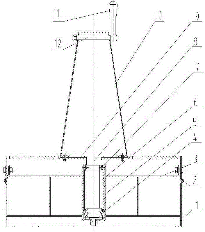
[0014] figure 1 It is the cable retractable bracket of the present invention, and the cable retractable bracket includes a cylindrical bracket 1, a main shaft 8, a cable bearing plate 9, a tapered winding column 10, and a winding handle 11. The circular The cylinder bracket 1 is composed of frame support ribs 3 and folding handle 2; the main shaft 8 is arranged on the coaxial line inside the cylinder bracket 1, and the periphery of the main shaft 8 is provided with a support tube 5, and the inner wall of the support tube 5 is fixedly connected with a shaft sleeve 6. The upper end of the support cylinder 5 is provided with a deep groove ball bearing 7, and the lower end is provided with a bearing 4, and the deep groove ball bearing 7 is coaxially arranged with the bearing 4; The top end is fixedly connected with the cable carrying plate 9, the lower end of the main shaft 8 is connected with the frame support rib 3, the tapered winding post 10 is placed on the cable carrying pla...


PUM


Abstract

The invention provides a cable take-up and pay-off bracket. A cylindrical bracket body in the bracket is composed of framework support ribs and folding handles. A main shaft is arranged in the coaxial line inside the cylindrical bracket body. A support barrel is arranged on the periphery of the main shaft. The inner wall of the support barrel is fixedly connected with a shaft sleeve. Deep groove ball bearings are arranged at the upper end of the inside of the support barrel, bearings are arranged at the lower end of the inside of the support barrel, and the deep groove ball bearings and the bearings are arranged coaxially. A cable bearing plate is arranged on the upper end surface of the cylindrical bracket body. The top end of the main shaft is fixedly connected with the cable bearing plate, and the lower end of the main shaft is connected with the framework support ribs. A conical wire wrapping post is placed on the cable bearing plate. The lower end of the conical wire wrapping post is connected with the cable bearing plate through nuts, a wire wrapping handle is installed at the upper end of the conical wire wrapping post, and the installed wire wrapping handle is connected with the conical wire wrapping post through a handle pin. According to the cable take-up and pay-off bracket, the structure is simple, the implementation is easy, the working efficiency is improved, and the labor intensity is relieved.

Description

technical field [0001] The invention belongs to the technical field of cable fixing devices, and in particular relates to a cable retractable bracket. Background technique [0002] In the measurement of pulsed radiation signals, coaxial cables of various sizes are usually used for signal transmission. For coaxial cables with a diameter greater than 12mm, relatively heavy or even huge cable reels and special bearing support systems are generally used for retracting and moving. , Transportation, and recycling often require the cooperation of multiple people; coaxial cables or general thin cables with a diameter of less than 3mm, due to their small diameter, light weight, and soft cables, generally can use a wide variety of general-purpose cable retractors on the market , even manually can be retracted and retracted directly. During the retracting process, moving, transporting, and recycling basically require the cooperation of multiple people; The twisting force is generated,...

Claims


Application Information

Patent Timeline
Patent Type & Authority Applications(China)
IPC IPC(8): B65H75/38B65H75/44
Inventor 王文川章法强胡梦春李名加朱文华张震赵学水杨光玲蔡易平
Owner INST OF NUCLEAR PHYSICS & CHEM CHINA ACADEMY OF
Why Eureka
Try Eureka