
Tilt-rotor based on combination of four rotor wings and fixed wing

A technology of tilt-rotor and fixed-wing, which is applied in the direction of aircraft, rotorcraft, motor vehicles, etc., and can solve the problems of unstable flight of two-rotor aircraft, complex tilting mechanical structure, and application restrictions of tilt-rotor aircraft.

Inactive Publication Date: 2016-02-03
NANCHANG HANGKONG UNIVERSITY
View PDF0 Cites 16 Cited by
  • Summary
  • Abstract
  • Description
  • Claims
  • Application Information

AI Technical Summary

Problems solved by technology

Most of the existing tilt-rotor aircraft are two-axis tilting, such as the MV-22 of the United States. The disadvantage of this type of tilt-rotor aircraft is that the load capacity of the aircraft is very limited during vertical take-off and landing, and the two-rotor aircraft is relatively unstable when flying
At the same time, the existing tilting rotorcraft tilting mechanical structure is complex and the tilting process is not safe
It is precisely because of the above-mentioned shortcomings that the application of tilt-rotor aircraft is greatly limited

Method used


Image

  • Tilt-rotor based on combination of four rotor wings and fixed wing
  • Tilt-rotor based on combination of four rotor wings and fixed wing
  • Tilt-rotor based on combination of four rotor wings and fixed wing

Examples


Embodiment Construction

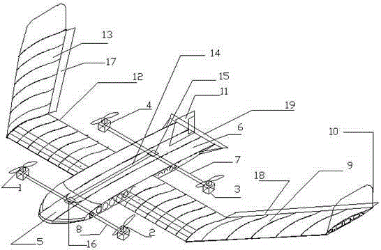
[0020] The present invention is described in detail below in conjunction with accompanying drawing; figure 1 , figure 2 and image 3 As shown, the present invention is a tilt-rotor aircraft based on the combination of quadrotor and fixed wing. The front sections of the fuselage 5 and 6 are symmetrically installed with the first and second motors through the external tilting transmission shaft 8, and the middle sections of the fuselage 5 and 6 pass through The main beam is installed with the middle transverse wing 12, the rear ends of the fuselage 5 and 6 are symmetrically installed with the third and fourth motors through the external tilting transmission shaft 7, and the inside of the fuselage 5 and 6 is longitudinally installed with the internal tilting transmission shaft 14 and the transmission Gear 15,16, fuselage 5,6 rear ends install horizontal empennage 19 and vertical empennage 11. Swept wings 9 and 13 are respectively installed symmetrically with a sweep angle of ...


PUM


Abstract

The invention discloses a tilt-rotor based on combination of four rotor wings and a fixed wing. The tilt-rotor is structurally characterized in that a first rotor wing, a second rotor wing, a third rotor wing and a fourth rotor wing are divided into two groups which are respectively symmetrically mounted on the two sides of a tilt-rotor body by two shafts; (1, 2) is a front motor group; (3, 4) is a rear motor group; a middle wing is horizontally mounted on the tilt-rotor body and is vertical to the tilt-rotor body; backswept wings on the two sides are respectively mounted on the two sides of the middle horizontal wing at a backswept angle of 50 degrees. According to the tilt-rotor disclosed by the invention, the four rotor wings and the fixed wing are enabled to share a set of power system to realize vertical takeoff and landing, hovering and cruise level flying; the front and rear tilting motor groups (1, 2) and (3, 4) share a set of tilting device to realize synchronous tilting by a tilting drive shaft, thereby simplifying a tilting structure and improving the operability and stability of the tilt-rotor.

Description

technical field [0001] The invention relates to aircraft design technology, in particular to a tilt-rotor aircraft based on the combination of four rotors and fixed wings. Background technique [0002] Since the take-off and landing of fixed-wing aircraft are largely restricted by the site, a specific runway is often required for take-off and landing, and it cannot hover in the air, so it cannot perform some specific flight tasks. [0003] None of the four rotors of a traditional quadrotor aircraft can tilt forward or backward. On the one hand, when it realizes horizontal forward flight, the speed of the two rotors at the front end of the fuselage is required to decrease, while that at the rear end of the fuselage The speed of the two rotors increases, so that the lift difference due to the different speeds of the front and rear rotors will inevitably lead to the pitching motion of the fuselage, so that the aircraft's horizontal forward flight and vertical lift will affect e...

Claims


Application Information

Patent Timeline
Patent Type & Authority Applications(China)
IPC IPC(8): B64C27/22B64C27/26
Inventor 王庆蔡志华陶则旭王春琦邓俊郑心远淦亚苹韩亮史彧铭白鹤
Owner NANCHANG HANGKONG UNIVERSITY
Learn More