Supercharge Your Innovation With Domain-Expert AI Agents!
A head body of a three-layer co-extrusion film blowing unit
What is Al technical title?
Al technical title is built by PatSnap Al team. It summarizes the technical point description of the patent document.
A three-layer co-extrusion and die head technology is applied in the field of the die body of a three-layer co-extrusion film blowing unit, which can solve the problems of large difference in channel length, uneven distribution of film materials, and complicated assembly, so as to achieve high product quality. , The effect of good processing effect, convenient maintenance and repair
Active Publication Date: 2018-04-06
嘉兴高正新材料科技股份有限公司
View PDF7 Cites 2 Cited by
Summary
Abstract
Description
Claims
Application Information
AI Technical Summary
This helps you quickly interpret patents by identifying the three key elements:
Problems solved by technology
Method used
Benefits of technology
Problems solved by technology
[0002] The head of a multi-layer co-extrusion blown film machine usually includes a mandrel, an outer die, an inner die, an extrusion sleeve and an inlet die. There are blowing passages connected between the mandrel and the inner die. A discharge channel is provided between the outgoing die head and the internal die head. However, in the existing multi-layer co-extrusion film blowing machine head, the extrusion sleeve is provided with a certain number, and the extrusion material of the several number The axial direction of the mandrel is sequentially stacked on the outside of the mandrel, and the die head is correspondingly arranged on the outside of the extrusion sleeve. In this scheme, each layer of film material is compounded in a layer-by-layer manner. The channel lengths of the layers of film materials are quite different, which makes the distribution of film materials in each layer difficult to be uniform, and each extrusion sleeve is assembled layer by layer in the axial direction of the mandrel, which has the disadvantage of cumbersome assembly.
Method used
Image
Click on the blue label to locate the original text in one second.
Reading with bidirectional positioning of images and text.
Examples
Embodiment
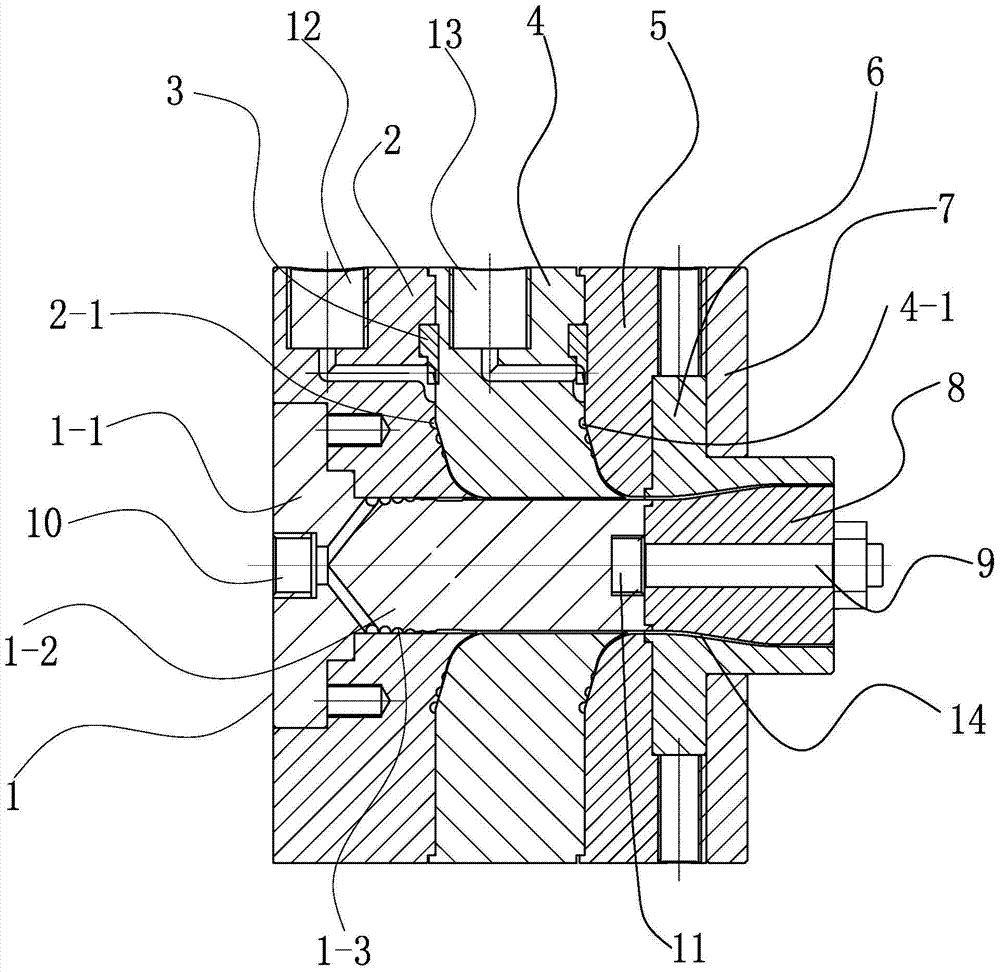
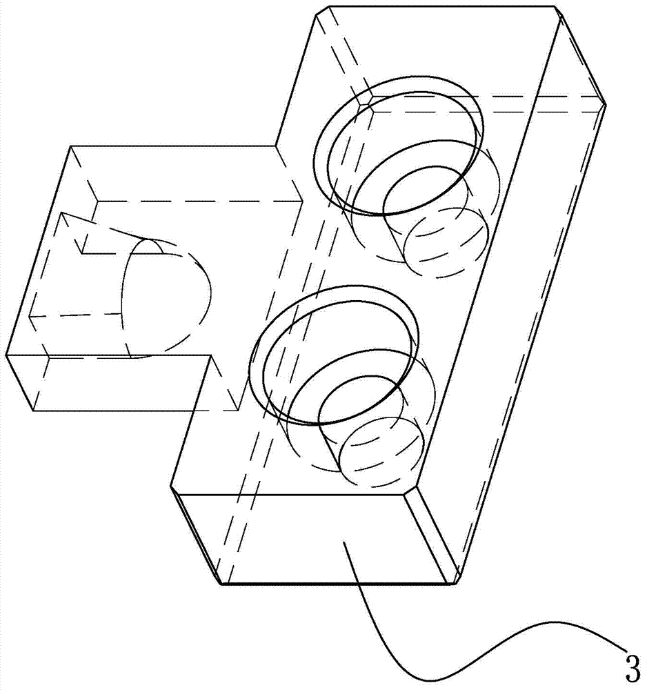
[0016] Example: such as figure 1 Shown: a head body of a three-layer co-extrusion film blowing unit, including a spiral body 1, an inner die head 2, a middle die head 4, an outer die head 5, a die 6 and a pressure plate 7, the spiral body 1, the inner die head 2. The middle die head 4, the outer die head 5, the mouth die 6 and the pressure plate 7 are arranged sequentially along the length direction from left to right. The spiral body 1 is located in the middle of the die body and is composed of two parts, namely the vertical part 1-2. And the extension part 1-1 extending outward from its lower part, and the outer wall of the vertical part 1-2 is provided with a first helical groove 1-3, and the lower end of the vertical part 1-2 of the spiral body 1 sets an axial connection inward Hole 10, the top of the connecting hole 10 is provided with an axial first feed channel 11 inwardly, and the spiral body 1 is connected to the inner die head 2, the middle die head 4, and the outer ...
PUM
Abstract
The invention relates to a handpiece body of a three-layer coextrusion film blowing unit. The handpiece body of the three-layer coextrusion film blowing unit comprises a spiral body, an inner die head, a middle die head, an outer die head, a mouth die and a pressing plate, wherein the spiral body, the inner die head, the middle head, the outer die head, the mouth die and the pressing plate are orderly distributed from left to right along the length direction, the spiral body is arranged in the middle of the handpiece body, and comprises two parts which are a vertical portion and an extension portion, the lower portion of the extension portion outwardly extends, a first spiral slot is arranged on the outer wall of the vertical portion, an axial connecting hole is inwardly arranged on the lower end of the vertical portion of the spiral body, and a first feeding channel is inwardly arranged on the top end of the axial connecting hole in the axial direction. The handpiece body of the three-layer coextrusion film blowing unit can achieve to process composite packing films such as low-density polyethylene (LDPE), high-density polyethylene (HDPE), linear low density polyethylene (LLDPE), ethylene vinyl acetate (EVA) and the like, is beneficial for high speed composite, uses multiple colors to print, and is excellent in composite effect, high in product quality, convenient in maintenance and repair and long in service life.
Description
technical field [0001] The invention relates to mechanical processing equipment, in particular to a machine head body of a three-layer co-extruded film blowing unit. Background technique [0002] The head of a multi-layer co-extrusion blown film machine usually includes a mandrel, an outer die, an inner die, an extrusion sleeve and an inlet die. There are blowing passages connected between the mandrel and the inner die. A discharge channel is provided between the outgoing die head and the internal die head. However, in the existing multi-layer co-extrusion film blowing machine head, the extrusion sleeve is provided with a certain number, and the extrusion material of the several number The axial direction of the mandrel is sequentially stacked on the outside of the mandrel, and the die head is correspondingly arranged on the outside of the extrusion sleeve. In this scheme, each layer of film material is compounded in a layer-by-layer manner. The channel lengths of the layer...
Claims
Application Information
Patent Timeline
Application Date:The date an application was filed.
Publication Date:The date a patent or application was officially published.
First Publication Date:The earliest publication date of a patent with the same application number.
Issue Date:Publication date of the patent grant document.
PCT Entry Date:The Entry date of PCT National Phase.
Estimated Expiry Date:The statutory expiry date of a patent right according to the Patent Law, and it is the longest term of protection that the patent right can achieve without the termination of the patent right due to other reasons(Term extension factor has been taken into account ).
Invalid Date:Actual expiry date is based on effective date or publication date of legal transaction data of invalid patent.
