
Crankshaft placing rack

A technology for placing racks and crankshafts, applied in tool storage devices, manufacturing tools, etc., can solve problems such as inconvenient access for workers, mutual contact of crankshafts, damage to crankshafts, etc., to achieve avoiding random shaking, convenient access, and strong applicability Effect

Inactive Publication Date: 2016-02-03
CHONGQING CHUANGLONG IND
View PDF11 Cites 1 Cited by
  • Summary
  • Abstract
  • Description
  • Claims
  • Application Information

AI Technical Summary

Problems solved by technology

For example, in order to facilitate transportation, the blanks will be placed in the collection box and transferred to the finishing turning and fine grinding place. After the grinding is completed, they will be collected and transferred to the washing place. During this centralized collection process, the traditional The way is to put the crankshaft directly into the collection box. There are many disadvantages in this way, for example, the crankshafts will contact each other or even collide, which will damage the crankshaft and it is very inconvenient for workers to pick and place. Therefore, it is necessary to do out improvement

Method used


Image

  • Crankshaft placing rack
  • Crankshaft placing rack
  • Crankshaft placing rack

Examples


Embodiment Construction

[0015] The present invention will be described in further detail below by means of specific embodiments and reference numerals:

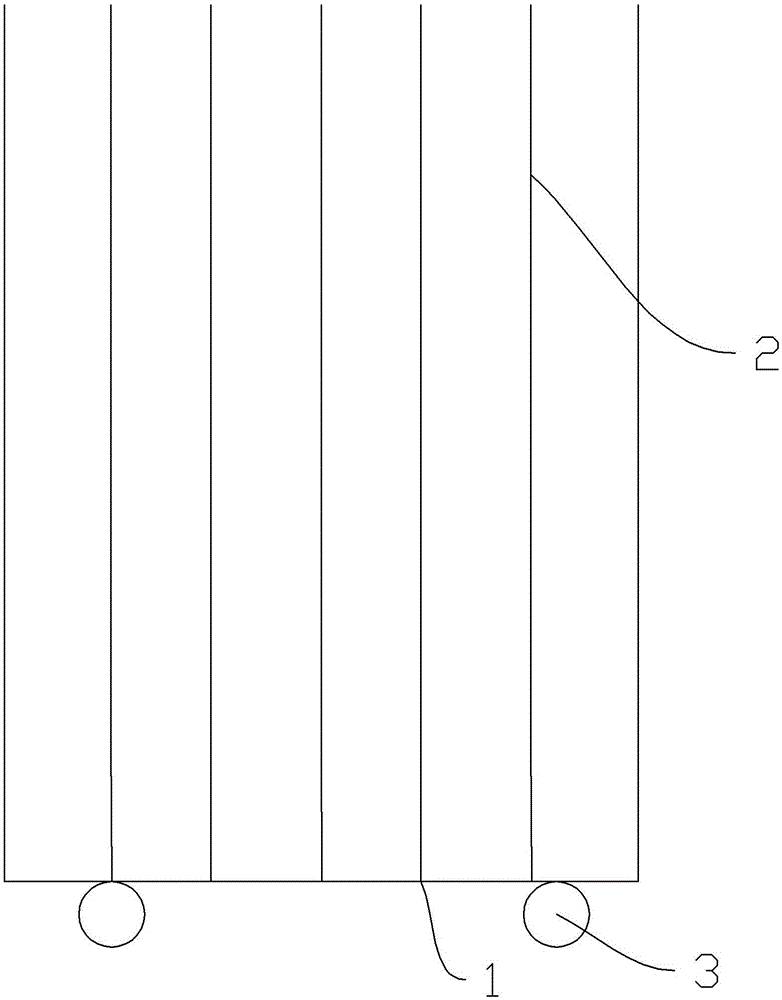
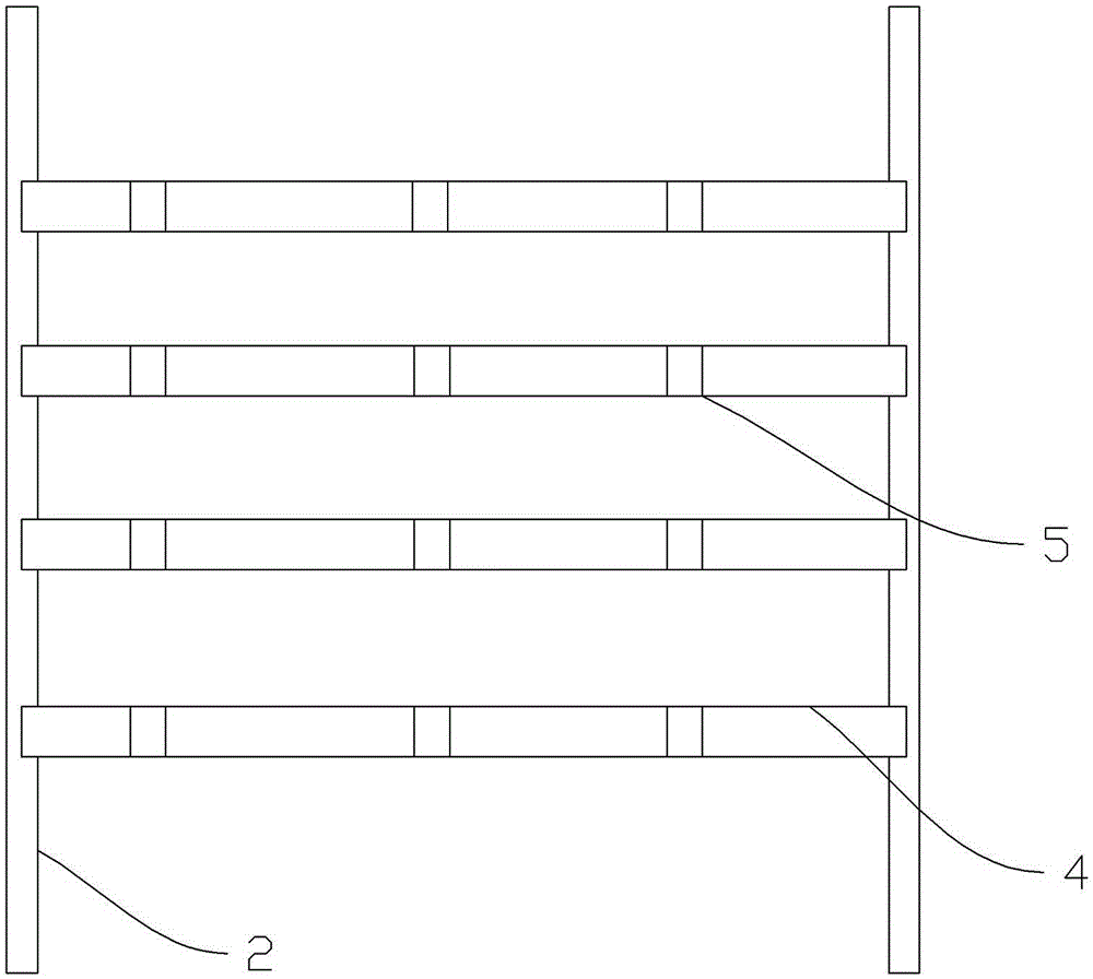
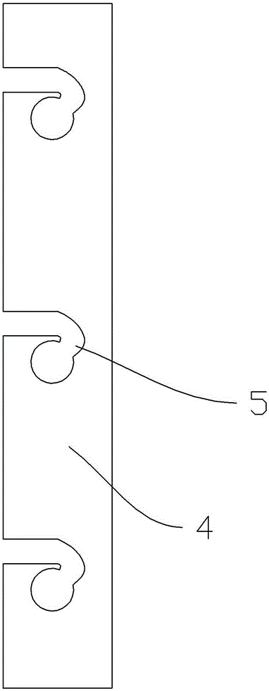
[0016] The reference signs in the accompanying drawings of the specification include: base 1 , mounting frame 2 , roller 3 , hanging beam 4 , and mounting hole 5 .

[0017] The embodiment is basically as attached figure 1 , figure 2 , image 3 Shown: including the base 1, two rows of parallel vertical mounting frames 2 are installed on the base 1, each row of mounting frames 2 has seven mounting frames 2, and the mounting frames 2 are evenly distributed along the vertical direction with four Draw-in slots, the distance between the upper and lower draw-in slots is greater than the length of the crankshaft, the draw-in slots on the two rows of installation frames 2 correspond one by one, and the corresponding two draw-in slots are equipped with horizontally placed hanging beams 4 between every two installation frames 2 Four hanging beams 4 are ins...


PUM


Abstract

The invention relates to the field of crankshaft stacking equipment, and specifically relates to a crankshaft placing rack. The crankshaft placing rack comprises a base, wherein two rows of vertical mounting racks which are parallel to each other are arranged on the base; clamping grooves are uniformly formed in the mounting racks along the vertical direction, and the distance from the upper clamping groove to the lower clamping groove exceeds the length of a crankshaft; the clamping grooves in the two mounting racks are corresponding to each other, and horizontally-positioned suspension beams are arranged in every two corresponding clamping grooves; mounting holes, comprising a feeding hole and a suspension hole which communicate with each other, are formed in the suspension beams; a plurality of hole channels with corners are arranged between the corresponding feeding hole and the corresponding suspension hole. The crankshaft placing rack has the advantages that a plurality of crankshafts can be synchronously suspended; each suspended crankshaft can be relatively positioned, so that the crankshafts cannot collide with each other; a suspension manner is adopted and enables convenient picking and placing and facilitates the operation of workers; the whole placing rack is simple in structure, and low in cost, and applicable to the placing and transferring of the crankshafts in each workshop.

Description

technical field [0001] The invention relates to the field of crankshaft stacking equipment, in particular to a crankshaft placement rack. Background technique [0002] The crankshaft is the most important part of the engine. It bears the force transmitted by the connecting rod and converts it into torque, which is output through the crankshaft and drives other accessories on the engine to work. The crankshaft is subjected to the combined action of the centrifugal force of the rotating mass, the periodically changing gas inertial force, and the reciprocating inertial force, so that the crankshaft is subjected to bending and torsional loads. Therefore, the crankshaft is required to have sufficient strength and rigidity, and the journal surface must be wear-resistant, work evenly, and Well balanced. The processing of the crankshaft mainly includes blank inspection, processing of blanks, finishing [0003] Turning, fine grinding, washing, polishing, inspection, anti-rust and o...

Claims


Application Information

Patent Timeline
Patent Type & Authority Applications(China)
IPC IPC(8): B25H3/04
CPCB25H3/04
Inventor 陈振丰
Owner CHONGQING CHUANGLONG IND
Learn More