A kind of multifunctional shoulder joint position frame
A shoulder joint, multi-functional technology, applied in the field of multi-functional shoulder joint body positioning frame, can solve the problems of surgical field pollution, difficult long-term effective realization of manual work, and long time for shoulder arthroscopic surgery, so as to improve surgical efficiency and reduce surgical infection Risk, the effect of reducing labor intensity
- Summary
- Abstract
- Description
- Claims
- Application Information
AI Technical Summary
Problems solved by technology
Method used
Image
Examples
Embodiment 1
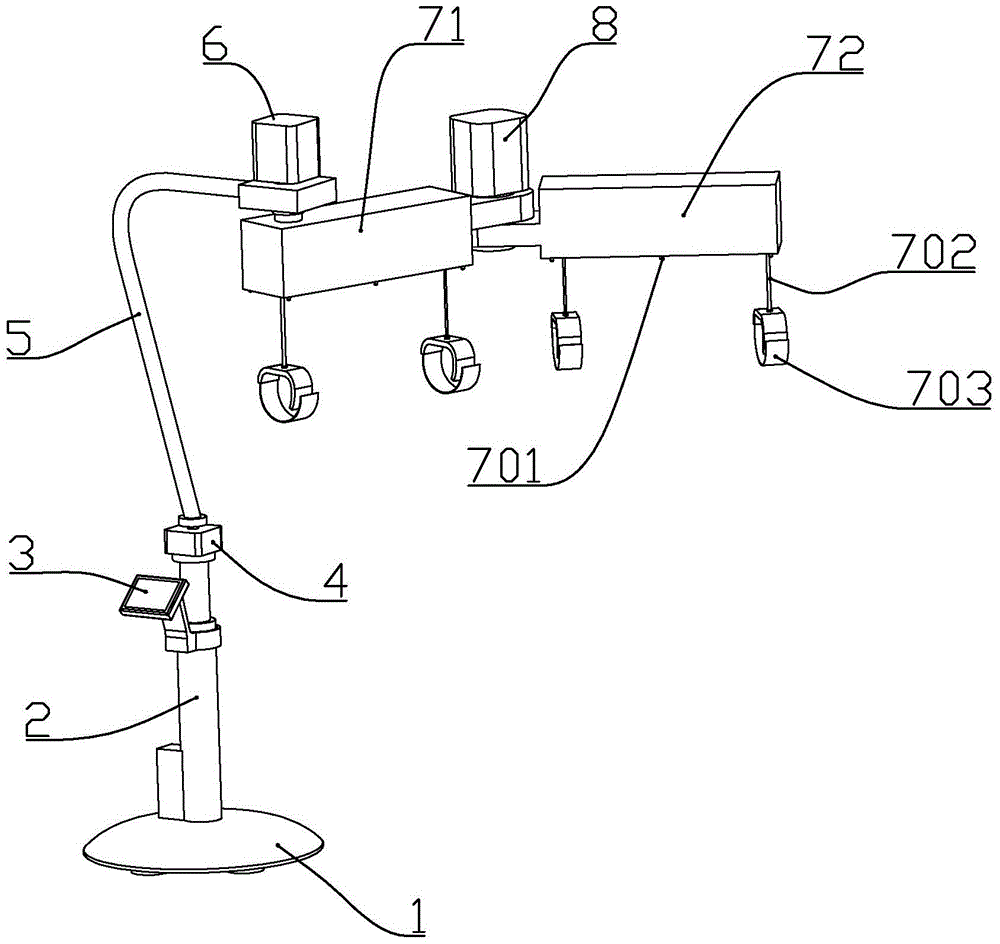
[0020] according to figure 1 and figure 2 As shown, a multifunctional shoulder joint body position frame described in this embodiment includes a base 1, a height adjustment push rod 2 vertically installed on the base, a control panel 3 installed on the side of the height adjustment push rod, fixedly connected The first motor 4 at the end of the output shaft of the height adjustment push rod is fixedly connected to the L-shaped support tube 5 on the output shaft of the first motor, the second motor 6 fixedly connected to the upper end of the support tube, and one end is connected to the second motor. The first rotating arm 71 fixedly connected to the output shaft, the third motor 8 fixedly connected to the other end of the first rotating arm, and the second rotating arm 72 fixedly connected to the output shaft of the third motor at one end; The output shafts of the second motor and the third motor are arranged vertically.
[0021] The bottom of the base is connected with 6-...
Embodiment 2
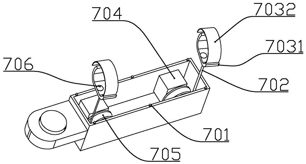
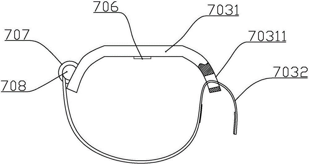
[0033] according to figure 1 , figure 2 and image 3 As shown, a multifunctional shoulder joint body position frame described in this embodiment includes a base 1, a height adjustment push rod 2 vertically installed on the base, a control panel 3 installed on the side of the height adjustment push rod, fixedly connected The first motor 4 at the end of the output shaft of the height adjustment push rod is fixedly connected to the L-shaped support tube 5 on the output shaft of the first motor, the second motor 6 fixedly connected to the upper end of the support tube, and one end is connected to the second motor. The first rotating arm 71 fixedly connected to the output shaft, the third motor 8 fixedly connected to the other end of the first rotating arm, and the second rotating arm 72 fixedly connected to the output shaft of the third motor at one end; The output shafts of the second motor and the third motor are arranged vertically.
[0034] The bottom of the base is conne...
PUM
 Abstract
Description
Claims
Application Information
 - R&D
- Intellectual Property
- Life Sciences
- Materials
- Tech Scout
- Unparalleled Data Quality
- Higher Quality Content
- 60% Fewer Hallucinations
Browse by: Latest US Patents, China's latest patents, Technical Efficacy Thesaurus, Application Domain, Technology Topic, Popular Technical Reports.
© 2025 PatSnap. All rights reserved.Legal|Privacy policy|Modern Slavery Act Transparency Statement|Sitemap|About US| Contact US: help@patsnap.com


