
A Variable Height Atomic Absorption Quartz Trap

An atomic absorption and trap technology, applied in the field of atomic absorption spectrometry, can solve the problems of not sharp enough absorption peaks and slow temperature changes, and achieve the effects of rapid temperature changes, sharp absorption peaks, and improved sensitivity

Active Publication Date: 2017-11-07
QIQIHAR UNIVERSITY
View PDF7 Cites 0 Cited by
  • Summary
  • Abstract
  • Description
  • Claims
  • Application Information

AI Technical Summary

Problems solved by technology

[0003] The present invention is to solve the problem that the existing quartz tube is controlled by gas-liquid exchange when collecting, resulting in slow temperature change and insufficient sharp absorption peak, and provides a variable-height atomic absorption quartz trap

Method used

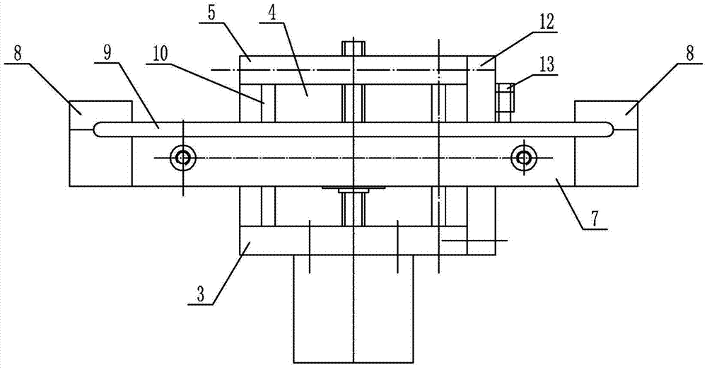
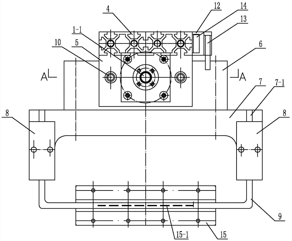

Image

  • A Variable Height Atomic Absorption Quartz Trap
  • A Variable Height Atomic Absorption Quartz Trap
  • A Variable Height Atomic Absorption Quartz Trap

Examples


specific Embodiment approach 1

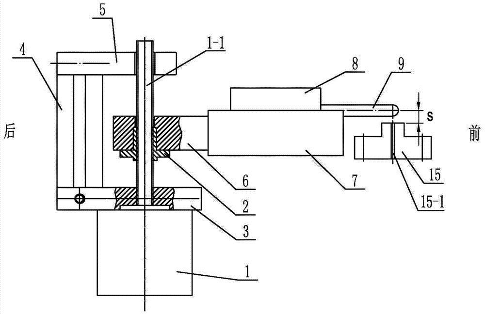
[0016] Specific implementation mode one: combine Figure 1 to Figure 8 Describe this embodiment, this embodiment includes stepper motor 1, Tr8 nut 2, motor plate 3, column 4, upper end plate 5, slider 6, groove type pipe frame 7, quartz collection pipe 9, channel steel 12, two A pipe clamp 8, two guide rods 10, two linear bearings 11, two limit switches 13 and two limit seats 14, the upper end plate 5 is arranged parallel to the motor plate 3 up and down, and the rear end of the slider 6 is located at the upper end Between the plate 5 and the motor plate 3, the stepper motor 1 is fixed on the lower end of the motor plate 3, and the screw 1-1 on the stepper motor 1 passes through the motor plate 3, the slider 6 and the upper end plate 5 in turn, and the Tr8 nut 2 is threadedly connected with the screw rod 1-1, and the Tr8 nut 2 is embedded in the slider 6, two guide rods 10 are symmetrically arranged on both sides of the screw rod 1-1, and each guide rod 10 is supported by a li...

specific Embodiment approach 2

[0019] Specific implementation mode two: combination image 3 The present embodiment will be described. The distance s from the upper end surface of the combustion head 15 to the centerline of the groove-shaped quartz collection tube 9 in this embodiment is 3 mm to 5 mm. This numerical range can guarantee that the quartz trapping tube 9 has an optimal trapping temperature. Other components and connections are the same as those in the first embodiment.

specific Embodiment approach 3

[0020] Specific implementation mode three: combination image 3 The present embodiment will be described. The distance s from the upper end surface of the combustion head 15 to the centerline of the grooved quartz collection tube 9 in the present embodiment is 3.52 mm. This value can guarantee that the quartz trapping tube 9 has an optimal trapping temperature. Other components and connections are the same as those in the second embodiment.


PUM

PropertyMeasurementUnit
diameteraaaaaaaaaa

Abstract

A variable-height atomic absorption quartz trap relates to an atom trap with a quartz tube used in a flame atomic absorption spectrometer. The upper end plate is set parallel to the motor plate up and down, the rear end of the slider is located between the upper end plate and the motor plate, the stepping motor is fixed on the lower end of the motor plate, and the screw on the stepping motor passes through the motor plate, the slider and the On the upper end plate, the Tr8 nut (2) is threadedly connected with the lead screw, and the Tr8 nut is embedded in the slider, each guide rod is supported in the slider through a linear bearing, and the column is located behind the slider and is set between the motor plate and the Between the upper end plates, the grooved pipe frame is set in front of the slider, the semicircular upper groove on the pipe clamp is fastened with the semicircular lower groove on the grooved pipe frame, and the two ends of the quartz collection tube They are respectively arranged in two semicircular lower grooves, the combustion head is placed under the quartz collection tube, and the combustion slit is directly opposite to the center line of the quartz collection tube. The invention is used for flame atomic absorption.

Description

technical field [0001] The invention relates to a quartz tube atom trap used in a flame atomic absorption spectrometer, belonging to the field of atomic absorption spectroscopic analysis, in particular to a variable-height atomic absorption quartz trap. Background technique [0002] When the known quartz tube atom trap for flame atomic absorption spectrometer is caught, water passes through the quartz trap tube, and the atoms are trapped on the surface of the quartz tube after cooling down; when the trap is released, the air passes through the quartz trap tube to drive off the water , and then stop the air flow, within a few seconds after heating up, the atoms trapped on the surface of the quartz tube will be released into the flame, resulting in sharp line absorption. The quartz tube on the existing quartz tube atom trap used for the flame atomic absorption spectrometer is parallel and horizontal on the acetylene inner flame above the combustion slit of the combustion head....

Claims


Application Information

Patent Timeline
Patent Type & Authority Patents(China)
IPC IPC(8): G01N21/31G01N21/01G01J3/42
Inventor 郑永杰田景芝王丹丹荆涛王梅梅
Owner QIQIHAR UNIVERSITY
Learn More