Fluid damper device and machine equipped with damper
A buffer device and fluid technology, applied in the field of equipment with buffer, can solve problems such as deviation, valve core 50x cannot be turned into a closed position, and load cannot be applied to rotating shaft 40x, so as to achieve the effect of suppressing warping
- Summary
- Abstract
- Description
- Claims
- Application Information
AI Technical Summary
Problems solved by technology
Method used
Image
Examples
Embodiment approach 1
[0052] (the overall structure of the buffered equipment and the fluid buffer device 10)
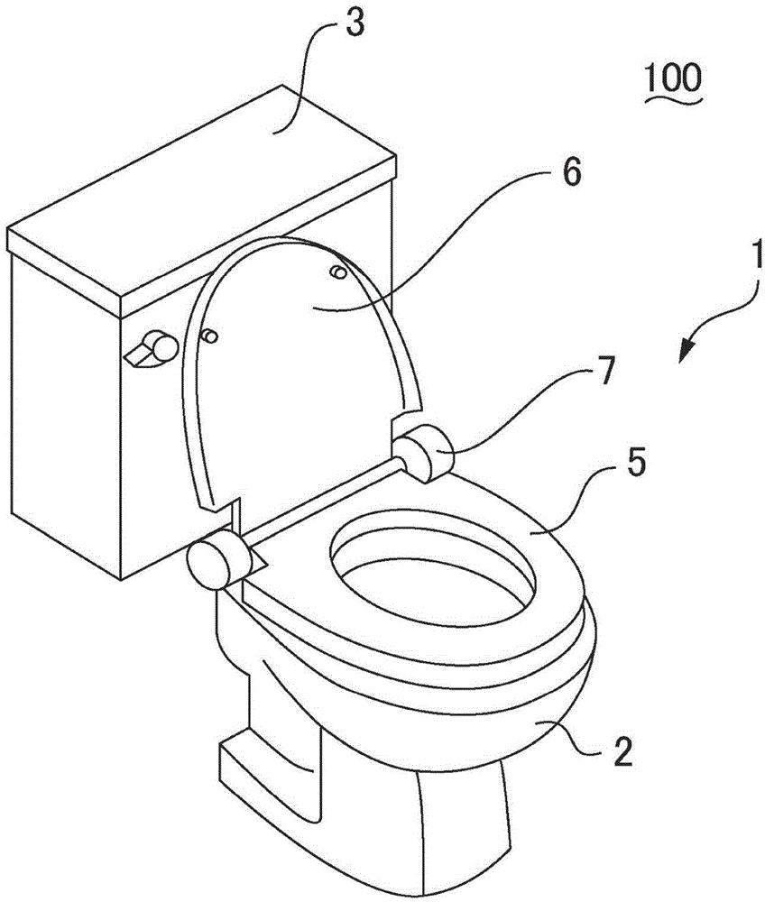
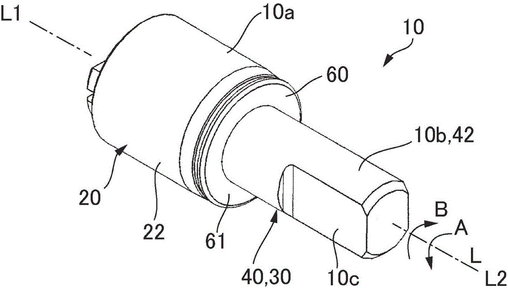
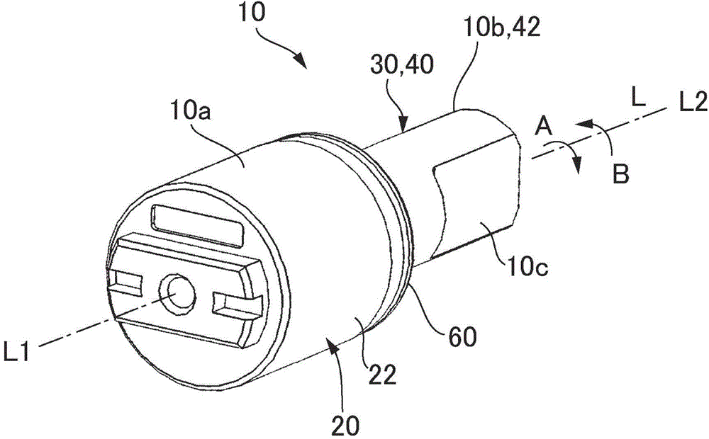
[0053] figure 1 It is explanatory drawing of the western-style toilet unit 100 which has the western-style toilet 1 equipped with the fluid cushioning device 10 which concerns on Embodiment 1 of this invention. 2(a) and 2(b) are perspective views of the fluid cushioning device 10 according to Embodiment 1 of the present invention, and FIG. 2(a) is the fluid cushioning device 10 viewed from the other side L2 in the axis L direction. 2(b) is a perspective view of the fluid buffer device 10 viewed from one side L1 in the direction of the axis L.
[0054] figure 1 The western style toilet unit 100 shown includes a western style toilet 1 (cushioned equipment) and a sink 3 . The Western-style toilet 1 includes a toilet body 2 , a resin toilet seat 5 (lid member), a resin toilet lid 6 (lid member), a unit cover 7 , and the like. Inside the unit cover 7 are built-in fluid cushioning devices f...
Embodiment approach 2
[0093] Figure 7 It is an explanatory view enlargedly showing the valve body 50 and the valve body supporting portion 460 of the fluid shock absorbing device 10 according to Embodiment 2 of the present invention. In addition, in Figure 7 , shows a state where the spool 50 is in an open posture. In Embodiment 1, the receiving portion 466 formed on the first convex portion 461 receives the entire protruding portion 52 of the valve element 50 when the valve element 50 is in the closed posture. Figure 7 As shown, a gap S may be formed between the receiving portion 466 formed on the first convex portion 461 and the valve body 50 , and in the vicinity of the boundary between the base portion 51 and the protruding portion 52 . Even with such a structure, in the open position, since the inner part 520 of the protruding part 52 of the valve body 50 is formed on the first convex part 461 of the rotary shaft 40 from the first part 521 to the second part 522 of the protruding part 52 ...
Embodiment approach 3
[0095] Figure 8 It is an explanatory view enlargedly showing the valve body 50 and the valve body supporting portion 460 of the fluid shock absorber 10 according to Embodiment 3 of the present invention. In addition, in Figure 8 , shows a state where the spool 50 is in an open posture. In Embodiment 1, the entire radially outer end portion 465 of the first protrusion 461 serves as the receiving surface 466a, but in this embodiment, as Figure 8 As shown, a part 465 a of the end portion 465 is located radially inward of the receiving surface 466 a and is separated from the protruding portion 52 . More specifically, a portion 465 a of the end portion 465 that overlaps with the vicinity of the boundary between the base portion 51 and the protruding portion 52 in the second direction B is located radially inward of the receiving surface 466 a and separated from the protruding portion 52 . Even with such a structure, in the open position, the inside portion 520 of the protrudi...
PUM
 Abstract
Description
Claims
Application Information
 - R&D Engineer
- R&D Manager
- IP Professional
- Industry Leading Data Capabilities
- Powerful AI technology
- Patent DNA Extraction
Browse by: Latest US Patents, China's latest patents, Technical Efficacy Thesaurus, Application Domain, Technology Topic, Popular Technical Reports.
© 2024 PatSnap. All rights reserved.Legal|Privacy policy|Modern Slavery Act Transparency Statement|Sitemap|About US| Contact US: help@patsnap.com


