
Low-lift high-flow liquid delivery device

A conveying device and large flow technology, which is applied to components of pumping devices for elastic fluids, pump devices, liquid fuel engines, etc., and can solve problems such as unfavorable water body ecological environment, small biological damage, and high power of axial flow pumps , to achieve the effects of being eco-friendly, reducing damage, and operating with low noise

Active Publication Date: 2016-01-27
NINGBO ZHICHUNREN ENVIRONMENTAL ENG CO LTD
View PDF6 Cites 0 Cited by
  • Summary
  • Abstract
  • Description
  • Claims
  • Application Information

AI Technical Summary

Problems solved by technology

Therefore, the use of axial flow pumps to create flow in river water will cause a lot of waste of electric energy and high operating costs.
In addition, due to the high power and high speed of the axial flow pump, the noise during operation is relatively large; and due to the high speed of the axial flow pump, the impeller will cause great damage to small organisms in the river water body during operation, which is not conducive to building Good water ecological environment

Method used


Image

  • Low-lift high-flow liquid delivery device
  • Low-lift high-flow liquid delivery device
  • Low-lift high-flow liquid delivery device

Examples


Embodiment 1

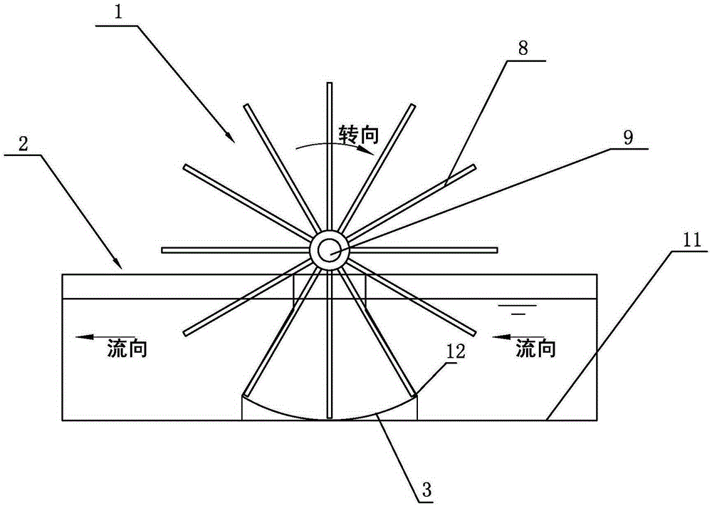
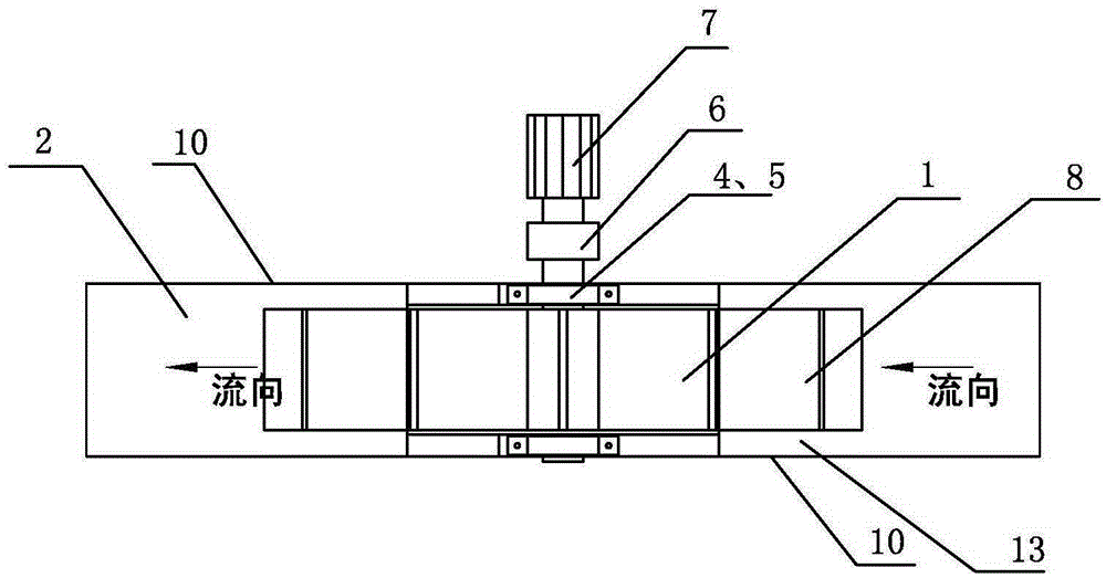
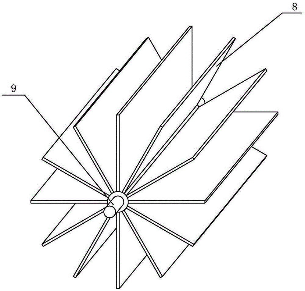
[0024] Embodiment one: see Figure 1-4 , a low-lift large-flow liquid delivery device, including a flow channel 2 composed of a bottom surface 11 and two side surfaces 10, and an impeller 1 arranged above the flow channel 2. The impeller 1 is composed of a rotating shaft 9 and ten uniformly arranged around the rotating shaft Consisting of two planar equal-length panels 8, the rotating shaft 9 is supported on the two sides 10 of the flow channel through the bearing 4 and the bearing seat 5, and the rotating shaft 9 is connected with a rotating driving device composed of a reduction device 6 and a motor 7 , the bottom surface 11 is provided with an arc surface 3 below the impeller 1, the center of the arc surface 3 coincides with the center of the rotating shaft 9, the center angle of the arc surface 3 is equal to 60 degrees, and between the arc surface 3 and the web 8 A lower gap 12 is provided, a side gap 13 is provided between the side surface 10 and the web 8, a flexible low...

Embodiment 2

[0025] Embodiment 2: Other structures are the same as Embodiment 1, the difference is that the web 8 is a curved surface, and the bending direction of the curved surface is opposite to the rotation direction of the impeller 1 .

Embodiment 3

[0026] Embodiment 3: Other structures are the same as Embodiment 1, except that side plates (not shown) are arranged on both sides of the blade, and the rotational speed of the impeller 1 is 5 rpm.


PUM


Abstract

The invention discloses a low-lift high-flow liquid delivery device. The low-lift high-flow liquid delivery device comprises a flow channel and an impeller, wherein the flow channel is composed of a bottom surface and two side surfaces; the impeller is arranged above the flow channel. The impeller is provided with a rotary driving device. The low-lift high-flow liquid delivery device is characterized in that the impeller is composed of a rotary shaft and a plurality of equilong center plates which are evenly arranged around the rotary shaft; the bottom surface is provided with an arc surface located below the impeller; the circle center of the arc surface and the center of the rotary shaft coincide; the central angle of the arc surface is larger than or equal to the value obtained after 360 degrees is divided by the number of the center plates; the output rotational speed of the rotary driving device is less than or equal to 60 rpm. The low-lift high-flow liquid delivery device has the advantages that the design of the low rotational speed less than 60 rpm is adopted; the high flow of the liquid delivery device is benefited by a water storage space formed among the impeller and all the surfaces of the flow channel; the liquid delivery device is high in efficiency, low in running noise and friendly to environment.

Description

technical field [0001] The invention relates to a liquid conveying device, in particular to a liquid conveying device with low head and large flow. Background technique [0002] In the ecological management of urban inland rivers, due to the slow flow of water bodies, the problems of black and odorous water bodies, algae growth and sediment deposition in rivers have been aggravated. Improving the fluidity of water bodies will effectively alleviate these problems. [0003] One way to improve the fluidity of urban inland river water is to pump the water from one end of the river to the other end, so that the water in the river can flow. The characteristics of the water transport are 0.1-0.3m low head and 1-10m 3 / s large flow. However, in the current liquid conveying device, the water body conveying with low lift and large flow is mainly accomplished by the axial flow pump. Through the study of the main parameters of the axial flow pump, it is not difficult to see that the h...

Claims


Application Information

Patent Timeline
IPC IPC(8): F04D13/06F04D29/42F04D29/24
Inventor 孙继辉
Owner NINGBO ZHICHUNREN ENVIRONMENTAL ENG CO LTD
Learn More