
Emitter coupling type amplification-based oscillation drive control system of energy-saving power grid

A technology of emitter coupling and drive control, applied in energy-saving control technology, power amplifier, reducing/preventing power oscillation, etc., can solve problems such as ineffective energy saving, improve accuracy and practicability, increase input resistance, The effect of stabilizing the static operating point

Inactive Publication Date: 2016-01-20
成都申川节能环保工程有限公司
View PDF0 Cites 0 Cited by
  • Summary
  • Abstract
  • Description
  • Claims
  • Application Information

AI Technical Summary

Problems solved by technology

[0004] The purpose of the present invention is to overcome the defect that energy saving can not be effectively realized in the frequency conversion energy saving street lamp control system in the current smart grid frequency conversion energy saving system, and to provide an energy saving power grid oscillation drive control system based on emitter coupling amplification

Method used


Image

  • Emitter coupling type amplification-based oscillation drive control system of energy-saving power grid
  • Emitter coupling type amplification-based oscillation drive control system of energy-saving power grid
  • Emitter coupling type amplification-based oscillation drive control system of energy-saving power grid

Examples


Embodiment

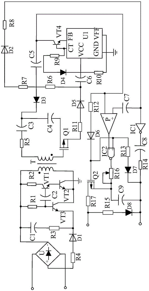
[0026] Such as figure 1 As shown, an energy-saving power grid oscillation drive control system based on emitter coupling amplification of the present invention consists of an EMI single-phase filter, a silicon-controlled rectifier connected with the EMI single-phase filter, and a silicon-controlled rectifier. The step-up power factor corrector, the single-phase high-frequency frequency converter connected with the step-up power factor corrector, the sampling protection circuit connected with the single-phase high-frequency frequency converter, the single-chip microcomputer connected with the sampling protection circuit, A band-pass filter low-distortion oscillating circuit connected in series between the step-up power factor corrector and the sampling protection circuit, a linear drive circuit connected in series between the sampling protection circuit and the single-chip microcomputer, and a single-phase high-frequency frequency converter connected in series It is composed of...


PUM


Abstract

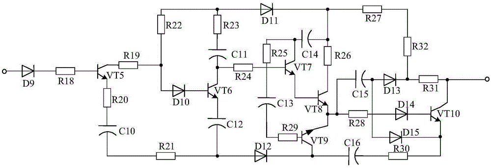
The invention discloses an emitter coupling type amplification-based oscillation drive control system of an energy-saving power grid. The system comprises an EMI single-phase filter, a silicon controlled rectifier, a boost-type power factor corrector, a single-phase high-frequency inverter, a sampling protection circuit connected with the single-phase high-frequency inverter, a single-chip microcomputer connected with the sampling protection circuit, a band-pass filtering low-distortion oscillating circuit in tandem connection between the boost-type power factor corrector and the sampling protection circuit, and a linear drive circuit in tandem connection between the sampling protection circuit and the single-chip microcomputer. The system is characterized in that an emitter coupling type amplification circuit is in tandem connection between the single-phase high-frequency inverter and the single-chip microcomputer. Since the linear drive circuit is adopted by the system, the control circuit of the above control system can be effectively and accurately driven. At the same time, the emitter coupling type amplification circuit is stable in static operating point, stable in output current and larger in input. Therefore, the energy-saving effect of the system is effectively improved.

Description

technical field [0001] The invention relates to the field of power grid energy saving, in particular to an energy-saving power grid oscillation drive control system based on emitter coupling amplification. Background technique [0002] At present, with the development of urbanization and the improvement of people's living standards, the power consumption of urban lighting has increased geometrically. In response to the call of the national energy conservation and emission reduction policy, the concept of smart grid has been increasingly recognized by everyone. The smart grid is the intelligence of the power grid, also known as "grid 2.0", which is a technical application based on an integrated, high-speed two-way communication network, which can realize the reliability, safety, economy, efficiency, environmental protection and safety of the power grid The goal. [0003] Among them, the frequency conversion energy-saving street lamp is an important unit of the smart grid, an...

Claims


Application Information

Patent Timeline
Patent Type & Authority Applications(China)
IPC IPC(8): H02J3/24H02J3/01H02M1/42H05B37/02H03F3/20
CPCY02B20/40Y02B70/10Y02E40/40
Inventor 钟黎
Owner 成都申川节能环保工程有限公司
Learn More