
Directional Dual Band Antenna

A dual-frequency antenna and transmission line technology, applied in the field of communication, can solve the problems of different wifi communication channels and increased costs

Active Publication Date: 2019-01-08
GENERAL TEST SYST
View PDF3 Cites 0 Cited by
  • Summary
  • Abstract
  • Description
  • Claims
  • Application Information

AI Technical Summary

Problems solved by technology

However, dual-band antennas can only work within a narrow bandwidth
Moreover, different countries and regions set up different 5G frequency bands, resulting in different wifi communication channels used in different countries and regions, and the working frequency bands of wifi antennas are also different, which increases the cost for manufacturers in design, manufacturing and other links

Method used


Image

  • Directional Dual Band Antenna
  • Directional Dual Band Antenna
  • Directional Dual Band Antenna

Examples


Embodiment Construction

[0034] Embodiments of the invention are described in detail below, examples of which are illustrated in the accompanying drawings. The embodiments described below by referring to the figures are exemplary and are intended to explain the present invention and should not be construed as limiting the present invention.

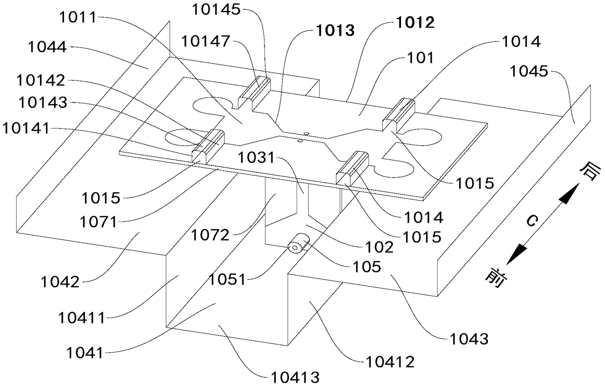
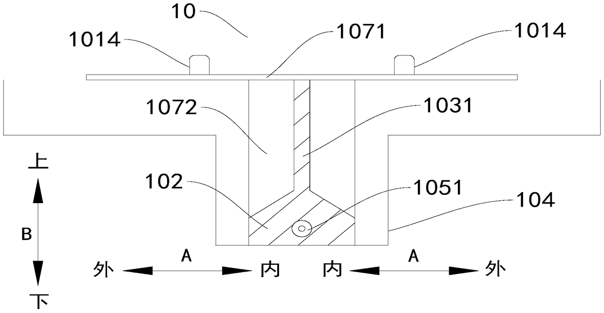
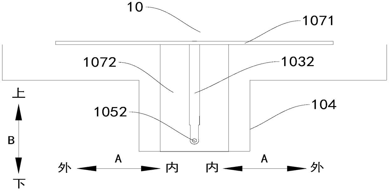
[0035] The following describes the directional dual-band antenna 10 according to the embodiment of the present invention with reference to the accompanying drawings. Such as Figure 1-Figure 9 As shown, the directional dual-band antenna 10 according to the embodiment of the present invention includes a radiator 101 , a microstrip balun 102 , a first transmission line 1031 , a second transmission line 1032 and a reflector 104 .

[0036] The radiator 101 has a slot 1011, a slit 1015 and a bent portion 1014, the inner end of the slit 1015 is connected to the slot 1011, the outer end of the slit 1015 is open, and the first edge of the bent portion 1014 is connected ...


PUM


Abstract

The invention discloses a directional dual-frequency antenna. The directional dual-frequency antenna comprises an irradiator, a microstrip Balun, a first transmission line, a second transmission line and a reflective plate, wherein the irradiator is provided with a groove, a gap and a bent part, the inner end of the gap is connected with the groove, the outer end of the gap is opened, a first edge of the bent part is connected with a first edge of the gap, and a second edge of the bent part is connected with a second edge of the gap; a first end of the first transmission line is connected with the irradiator, a second end of the first transmission line is connected with the microstrip Balun, and a first end of the second transmission line is connected with the irradiator; and the reflective plate is arranged below the irradiator, separated from the irradiator and connected with the microstrip Balun. According to the embodiment of the invention, the directional dual-frequency antenna has the advantages of ultra wide band, high gain, high front-to-back ratio, high axial cross polarization ratio, good consistency in directional diagram, small volume, simple structure, low manufacturing cost and the like, and is convenient to process.

Description

technical field [0001] The present invention relates to the communication field, in particular to a directional dual-frequency antenna. Background technique [0002] The wifi antenna is an indispensable part in the wifi communication link. Currently, existing wifi antennas include single-band antennas and dual-band antennas (such as Yagi antennas). However, dual-band antennas can only work within a narrow bandwidth. Moreover, different countries and regions set up different 5G frequency bands, resulting in different wifi communication channels used in different countries and regions, and the working frequency bands of wifi antennas are also different, which increases the cost for manufacturers in design, manufacturing and other links. Contents of the invention [0003] The present invention aims to solve one of the technical problems in the related art at least to a certain extent. For this reason, the present invention proposes a directional dual-frequency antenna with...

Claims


Application Information

Patent Timeline
Patent Type & Authority Patents(China)
IPC IPC(8): H01Q1/36H01Q1/50H01Q15/18H01Q19/13H01Q5/20
Inventor 漆一宏于伟
Owner GENERAL TEST SYST
Learn More