Tandem structure of RFID tags

A technology of radio frequency identification tags and series structure, which is applied in the direction of recording carriers, instruments, and calculations used by machines. It can solve the problems of not being able to determine oneself, potential safety hazards, and large randomness of movement paths, and achieve simple and convenient settings and changes. The effect of eliminating and eliminating the possibility of accidents

Active Publication Date: 2019-04-12
正量电子科技(苏州)有限公司 +3
View PDF5 Cites 0 Cited by
  • Summary
  • Abstract
  • Description
  • Claims
  • Application Information

AI Technical Summary

Problems solved by technology

2. Once the ground sense line is set, it is inconvenient to change and migrate
However, the ground sense wire is fixed on the ground and is easy to get involved in the lawn mower and be cut off, and it is a safety hazard, and it is easy to trip pedestrians
3. Although the robot lawn mower can determine the direction of the boundary through Ampere's law, it cannot determine its own position on the boundary, so returning to the starting point often requires a long-distance traversal of the boundary. Secondly, without the assistance of other technical means, its movement The path is too random, and there are uncoverable point blocks left in each job
However, Chinese patent application 201410420276.5 (2014, Xu Xiaomin) discloses a method of using RFID technology to guide the robot externally, which can also determine the boundary of the robot, but it requires a well-configured external antenna array, which is not suitable for outdoor home robot mowing. machine application scenarios

Method used


Image

  • Tandem structure of RFID tags
  • Tandem structure of RFID tags
  • Tandem structure of RFID tags

Examples


Embodiment Construction

[0022] The present invention will be described in further detail below in conjunction with the accompanying drawings and specific embodiments, so that those skilled in the art can better understand the present invention and implement it, but the examples given are not intended to limit the present invention. The following are descriptions of two examples.

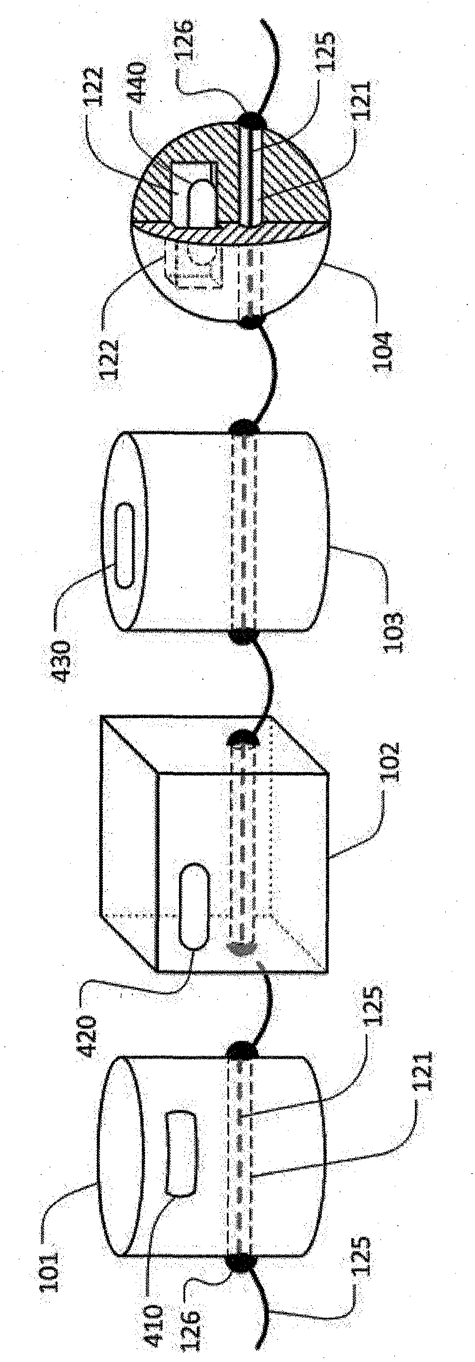
[0023] (1) The number of nodes in the series structure of the present invention is not less than 2, and it can be infinitely extended in theory. In this embodiment, the closed-loop serial structure is required to be 40 meters long, and the vertical axes of the nodes are equidistantly spaced at 20 cm, so there are a total of 200 node objects. figure 1 It is a four-node (101, 102, 103, 104) fragment of this serial structure: the node is connected with a rope (125) between the nodes; the node object has a through hole (121), and the rope passes through the through hole to connect the node; To prevent the node objects from sli...


PUM


Abstract

A series structure of a radio frequency identification label belongs to a radio frequency identification technology which is a robot correlation technology. By using the structure of the invention, setting, changing, revocation and migration problems of a working boundary of a robot mower are solved. The structure is designed on a bead-like structure; a radio frequency identification label is used to mark a node; a read-write memory of the radio frequency identification label is used to store identification codes of the radio frequency identification labels on adjacent nodes, a data linked list is established, a radio frequency identification label set which is connected in series on a logic aspect is formed, relations of physical positions of nodes on the class beading structure are mapped. A node object is made of a PVC material. The structure can be taken as a vector boundary of a robot working area or a guiding wire of blind person equipment. Corresponding equipment can grasp a direction of the boundary and an accurate position of the corresponding equipment on the boundary. Setting and changing of the structure are simple, the structure can be placed arbitrarily according to a job site and can be gathered and carried. One working boundary can be rapidly revoked or be migrated to another place so that there is no potential safety hazard.

Description

technical field [0001] The series structure of radio frequency identification tags belongs to radio frequency identification (RFID) technology, which is also a robot-related technology. Background technique [0002] Robot lawn mowers are self-propelled robots, and their range of activities or working boundaries need to be set manually. At present, there are two boundary setting methods for robot lawnmower products. One is to lay signal lines on the grass as the boundary, and the other is to define by GPS. Among them, GPS is calibrated with an accuracy of 3 meters in civilian use, which is not suitable for household lawnmower robots, so mainstream lawnmower robot products use the ground sense line boundary. However, the method of laying ground sense lines on the grass has great limitations: 1. The construction is relatively complicated and there are certain technical thresholds. The lawn mower robot determines the current direction of the ground sense wire and the direction...

Claims


Application Information

Patent Timeline
Patent Type & Authority Patents(China)
IPC IPC(8): G06K19/077
Inventor 许小敏赵琦伟梁寅
Owner 正量电子科技(苏州)有限公司
Why Eureka
Try Eureka