
Butterfly needle protective sleeve and butterfly needle assembly

A technology of protective sheath and butterfly needle, which is applied in the direction of needles and instruments introduced into the body, and can solve problems such as leakage, loose clamping structure, and easy-to-break protective sheath

Active Publication Date: 2016-01-20
杨松
View PDF10 Cites 5 Cited by
  • Summary
  • Abstract
  • Description
  • Claims
  • Application Information

AI Technical Summary

Problems solved by technology

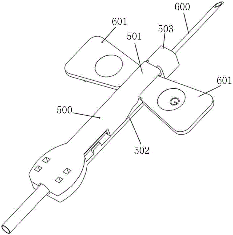
[0006] After the existing butterfly needle assembly is used, in the process of withdrawing the needle, as the fin 601 is receded along the linear direction of the slideway by external force, the locking structure of the rear ends of the upper cover 501 and the lower cover 502 is easily blocked by the flap 601. The back movement drives the pull to loosen or destroy the clamping structure
This needle withdrawal method is easy to damage the rear end connection of the upper cover 501 and the lower cover 502 of the protective sleeve 500
After the clamping of the rear ends of the upper cover 501 and the lower cover 502 fails, the used butterfly needle 600 will be exposed outside the protective cover 500, which will easily cause the risk of secondary accidental injury by the needle for subsequent medical waste disposal personnel
Moreover, even after the needle is withdrawn, the butterfly needle 600 does not exceed the needle tip protector 503, but the residual liquid in the butterfly needle 600 may leak from the needle tip protector 503, causing pollution

Method used


Image

  • Butterfly needle protective sleeve and butterfly needle assembly
  • Butterfly needle protective sleeve and butterfly needle assembly
  • Butterfly needle protective sleeve and butterfly needle assembly

Examples


Embodiment Construction

[0130] Example embodiments will now be described more fully with reference to the accompanying drawings. Example embodiments may, however, be embodied in many forms and should not be construed as limited to the embodiments set forth herein; rather, these embodiments are provided so that this disclosure will be thorough and complete, and will fully convey the concept of example embodiments to those skilled in the art. The same reference numerals denote the same or similar structures in the drawings, and thus their repeated descriptions will be omitted.

[0131]The described features, structures, or characteristics may be combined in any suitable manner in one or more embodiments. In the following description, numerous specific details are provided in order to give a thorough understanding of embodiments of the invention. However, those skilled in the art will appreciate that the technical solutions of the present invention may be practiced without one or more of the specific ...


PUM


Abstract

The invention provides a butterfly needle protective sleeve and a butterfly needle assembly; the butterfly needle protective sleeve comprises a protective sleeve body used for placing a butterfly needle; a needle withdraw channel is arranged in an axial direction in the protective sleeve body; the periphery of the protective sleeve body is provided with a slide way allowing wings of the butterfly needle to slide; the slide way comprises a pair of first slots arranged close to the far end of the protective sleeve body and keeping the wings to be in a usage state, a pair of second slots arranged close to the near end of the protective sleeve body and keeping the wings in a needle withdraw state, and a pair of stereo guiding connecting slots connected between the first slots and the second slots; the two opposite first slots are arranged on a first plane; the two opposite second slots are arranged on a second plane; the first plane intersects with the second plane; the stereo guiding connecting slots guide the wings to screw into the second slots from the first slots. The butterfly needle protective sleeve and butterfly needle assembly can effectively prevent needle heads of the butterfly needle from exposing under the needle withdraw state, so subsequent medical waste processing personnel cannot be accidentally secondarily injured by the needles.

Description

technical field [0001] The invention relates to the field of medical injection equipment, in particular to a butterfly needle protective cover and a butterfly needle assembly. Background technique [0002] The butterfly-shaped intravenous infusion needle is a clinical infusion device that has been widely used at present. Compared with traditional infusion equipment, the two-wing design of the butterfly-shaped handle is more firm and reliable when fixing the position of the intravenous infusion needle with adhesive tape. [0003] The butterfly-shaped intravenous infusion needle can provide an easy-to-install needle tip protection device, which can protect the sharp needle tip safely and reliably after the blood collection needle is used, reducing the secondary accidental injury of medical staff, patients, or subsequent medical waste disposal personnel by the needle risks of. [0004] However, the butterfly-shaped intravenous infusion needles in the prior art also have potent...

Claims


Application Information

Patent Timeline
IPC IPC(8): A61M5/158
Inventor 杨松田洪亮
Owner 杨松
Learn More